Hayward TriStar All TriStar models - Page 10
Shaft Seal Change Instructions cont'd. - parts
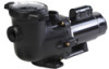 |
View all Hayward TriStar manuals
Add to My Manuals
Save this manual to your list of manuals |
Page 10 highlights
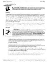
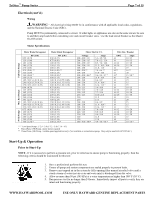
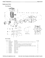
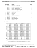
TriStar™ Pump Series Page 10 of 15 Shaft Seal Change Instructions (cont'd.) Removing the Motor Assembly (See Parts Diagram on page 11 of this manual for pump component locations.) 1. Remove the six (6) 5/16" x 2" hex head bolts (item #17), which hold the motor assembly to the pump/strainer housing (item #3), using a 1/2" wrench or socket. 2. Slide the motor assembly out of the pump/strainer housing (item #3), exposing the diffuser (item #9). Remove the two diffuser screws (item #7), and pull the diffuser (item #9) off of the seal plate (item #15) to expose the impeller (item #12). Removing the Impeller (See Parts Diagram on page 11 of this manual for pump component locations.) 3. Remove the motor canopy by removing the two (2) screws and pulling the canopy away from the motor. 4. To prevent motor shaft from turning, carefully place a 7/16" open-end wrench over the two (2) flats on the end of the shaft. 5. Rotate the impeller screw (item #10) clockwise (note that screw has left-hand thread) and remove. Remove the impeller (item #12) by rotating counterclockwise. Removing the Ceramic Seat (See Parts Diagram on page 11 of this manual for pump component locations.) 6. Remove the spring seal assembly (item #13) and seal plate (item #15) from the motor by removing the four (4) 3/8" x 1" bolts (item #18) that secure it to the motor, using a 9/16" wrench or socket. Remove the motor support bracket (item #20) from the seal plate (item #15). 7. Press the ceramic seat with rubber cup out of the seal plate (item #15). If tight, use a small screwdriver to tap seal out. STOP - Clean all recesses & parts to be reassembled. Inspect gaskets & replace if necessary. Seal Installation (See Parts Diagram on page 11 of this manual for pump component locations.) 8. Clean and lightly lubricate the motor shaft and seal recesses in the seal plate (item #15) with a dilute solution of nongranulated liquid-type soap. Gently wipe the polished face of the ceramic seal with a soft cotton cloth. Lubricate the rubber cup on the ceramic seat and press it firmly into the recess of the seal plate (item #15), with the polished ceramic surface facing out. 9. Reassemble the motor to the seal plate (item #15) using the four (4) 3/8" x 1" bolts (item #18), and re-attach the motor support (item #20) to the seal plate (item #15). 10. Gently wipe the black, polished surface of the spring seal assembly (item #13) with a soft cotton cloth. 11. Press the spring seal assembly (item #13) onto the motor shaft, with the black polished surface facing the ceramic seat. Replacing the Impeller and Diffuser (See Parts Diagram on page 11 of this manual for pump component locations.) 12. Screw the impeller (item #12) onto the motor shaft in a clockwise direction, and screw the impeller screw (item #10) into the motor shaft in a counterclockwise direction. Tighten snugly by holding motor shaft with wrench as noted in step #4. Place the impeller ring (item #11) back onto the impeller (item #12), with flange facing towards the diffuser (item #9). 13. Place the diffuser (item #9) over the impeller (item #12) and onto the seal plate (item #15), aligning the three pins on the diffuser (item #9) with the three holes on the seal plate (item #15). Replace the two diffuser screws (item #7). Replacing the Motor Assembly (See Parts Diagram on page 11 of this manual for pump component locations.) 14. Re-attach motor canopy using the two (2) hex headed screws. Slide the motor assembly, with the diffuser (item #9) in place, into pump/strainer housing (item #3), being careful not to disturb the diffuser gasket (item #8). 15. Fasten assembly to pump/strainer housing (item #3) using the six (6) 5/16" x 2" bolts (item #17). (Be sure housing gasket (item #14) is in place, and lubricated. Replace if damaged). Tighten bolts alternately and evenly to 185 inchpounds according to housing bolt torque pattern detail. WWW.HAYWARDPOOL.COM USE ONLY HAYWARD GENUINE REPLACEMENT PARTS
-
 1
1 -
2
-
3
-
4
-
 5
5 -
 6
6 -
 7
7 -
 8
8 -
 9
9 -
 10
10 -
 11
11 -
 12
12 -
 13
13 -
 14
14 -
 15
15
 |
 |