HealthRider Cc125 English Manual - Page 6
extending from the back of the Console. - where do the batteries go
 |
View all HealthRider Cc125 manuals
Add to My Manuals
Save this manual to your list of manuals |
Page 6 highlights
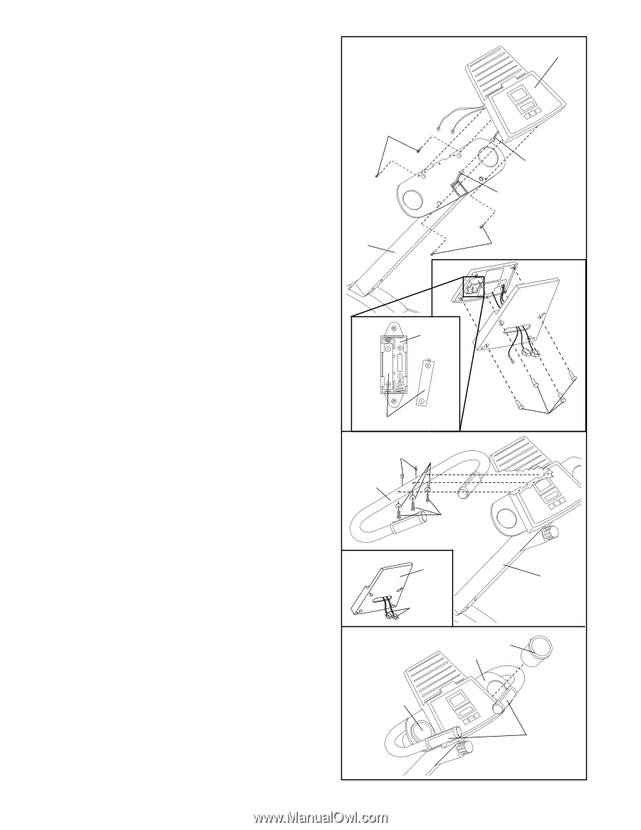
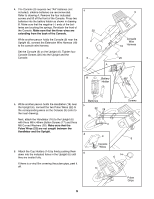
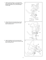
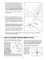
4. The Console (9) requires two ÒAAÓ batteries (not included); alkaline batteries are recommended. Refer to drawing A. Remove the four indicated screws and lift off the front of the Console. Press two batteries into the battery holder as shown in drawing B. Make sure that the negative (Ð) ends of the batteries are touching the springs. Re-attach the front of the Console. Make sure that the three wires are extending from the back of the Console. While another person holds the Console (9) near the Upright (6), connect the Extension Wire Harness (18) to the console wire harness. Set the Console (9) on the Upright (6). Tighten four Console Screws (20) into the Upright and the Console. 4 20 6 9 Console Wire 18 Harness 20 A B Battery Holder 5. While another person holds the Handlebar (16) near the Upright (6), connect the two Pulse Wires (22) to the corresponding wires on the Console (9) (refer to the inset drawing). Next, attach the Handlebar (16) to the Upright (6) with three M8 x 45mm Button Screws (17) and three M8 Curved Washers (28). Make sure that the Pulse Wires (22) are not caught between the Handlebar and the Upright. 6. Attach the Cup Holders (14) by firmly pushing them down into the indicated holes in the Upright (6) until they are seated fully. If there is a vinyl film covering the pulse grips, peel it off. Batteries 5 22 28 16 17 A 9 Console Wires 6 14 6 14 Screws 6 Pulse Grips 6
-
 1
1 -
 2
2 -
 3
3 -
 4
4 -
 5
5 -
 6
6 -
 7
7 -
 8
8 -
 9
9 -
 10
10 -
 11
11 -
 12
12 -
13
-
14
-
15
-
16
 |
 |