HP 1000-1300 Maintenance and Service Guide 1 - Page 50
Display assembly panel, from the system board.
 |
View all HP 1000-1300 manuals
Add to My Manuals
Save this manual to your list of manuals |
Page 50 highlights
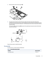
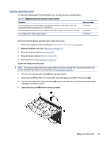
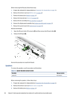
Display assembly panel To remove the display panel from the bottom cover, use this procedure and illustration. Table 5-8 Display assembly panel description and part number Description Spare part number 16.0 in Wide Quad Ultra Extended Graphics Array (WQUXGA), BrightView, (3840×2400), organic lightemitting diode (OLED) bent panel, eDP 1.4 + PSR, 400 nits 16.0 in Wide Quad Extended Graphics Array (WQXGA) (2560×1600), antiglare, non-touchscreen, 400 nits 16.0 in WQXGA (2560×1600), antiglare, 400 nits N13381-001 N13380-001 N13379-001 Before removing the display assembly panel, follow these steps: 1. Prepare the computer for disassembly (see Preparation for disassembly on page 33). 2. Remove the bottom cover (see Bottom cover on page 33). 3. Remove the battery (see Battery on page 34). 4. Remove the heat sink (see Heat sink on page 40). 5. Remove the fans (see Fan assembly on page 41) Remove the display assembly panel: NOTE: The camera module cable and antenna cables should have already been disconnected before this process when the right-side fan was removed. See Fan assembly on page 41. 1. Disconnect the display panel cable (1) from the system board. 2. Remove the six Phillips M2.0 × 4.5 screws that secure the display assembly to the top cover (2). 3. Swing the top edge of the display assembly (3) away from the top cover. (The display assembly hinges disengage from the top cover.) 4. Separate the top cover (4) from the display assembly. Display assembly panel 43
-
 1
1 -
2
-
3
-
4
-
5
-
6
-
7
-
8
-
9
-
10
-
11
-
12
-
13
-
14
-
15
-
16
-
17
-
18
-
19
-
20
-
21
-
22
-
23
-
24
-
25
-
26
-
27
-
28
-
29
-
30
-
31
-
32
-
33
-
34
-
35
-
36
-
37
-
38
-
39
-
40
-
41
-
42
-
43
-
44
-
 45
45 -
 46
46 -
 47
47 -
 48
48 -
 49
49 -
 50
50 -
 51
51 -
 52
52 -
 53
53 -
 54
54 -
 55
55 -
56
-
57
-
58
-
59
-
60
-
61
-
62
-
63
-
64
-
65
-
66
-
67
-
68
-
69
-
70
-
71
-
72
-
73
-
74
-
75
-
76
-
77
-
78
-
79
-
80
-
81
-
82
-
83
-
84
-
85
-
86
-
87
-
88
-
89
-
90
 |
 |