HP 1000-1300 Maintenance and Service Guide 1 - Page 59
RJ-45 door, Remove the fans see
 |
View all HP 1000-1300 manuals
Add to My Manuals
Save this manual to your list of manuals |
Page 59 highlights
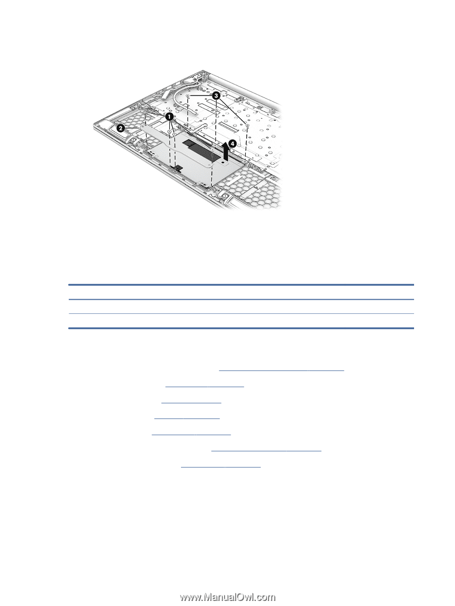
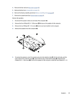
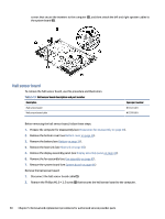
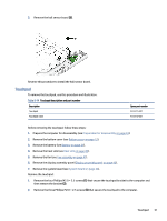
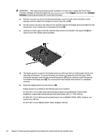
3. Remove the touchpad from the computer (4). Reverse this procedure to install the touchpad. RJ-45 door To remove the RJ-45 door, use this procedure and illustration. Table 5-15 RJ-45 door description and part number Description For 60 W models For 80 W models Spare part number N13385-001 N13386-001 Before removing the RJ-45 door, follow these steps: 1. Prepare the computer for disassembly (see Preparation for disassembly on page 33). 2. Remove the bottom cover Bottom cover on page 33(see ). 3. Remove the battery (see Battery on page 34). 4. Remove the heat sink (Heat sink on page 40). 5. Remove the fans (see Fan assembly on page 41). 6. Remove the display assembly panel (see Display assembly panel on page 43). 7. Remove the system board (see System board on page 44). Remove the RJ-45 door: 1. From the inside of the computer, insert a flat tool under the RJ-45 door (1). 52 Chapter 5 Removal and replacement procedures for authorized service provider parts
-
 1
1 -
2
-
3
-
4
-
5
-
6
-
7
-
8
-
9
-
10
-
11
-
12
-
13
-
14
-
15
-
16
-
17
-
18
-
19
-
20
-
21
-
22
-
23
-
24
-
25
-
26
-
27
-
28
-
29
-
30
-
31
-
32
-
33
-
34
-
35
-
36
-
37
-
38
-
39
-
40
-
41
-
42
-
43
-
44
-
45
-
46
-
47
-
48
-
49
-
50
-
51
-
52
-
53
-
 54
54 -
 55
55 -
 56
56 -
 57
57 -
 58
58 -
 59
59 -
 60
60 -
 61
61 -
 62
62 -
 63
63 -
 64
64 -
65
-
66
-
67
-
68
-
69
-
70
-
71
-
72
-
73
-
74
-
75
-
76
-
77
-
78
-
79
-
80
-
81
-
82
-
83
-
84
-
85
-
86
-
87
-
88
-
89
-
90
 |
 |