HP 1000-1300 Maintenance and Service Guide 1 - Page 60
Display assembly
 |
View all HP 1000-1300 manuals
Add to My Manuals
Save this manual to your list of manuals |
Page 60 highlights
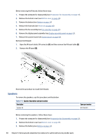
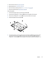
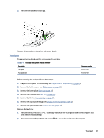
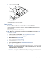
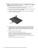
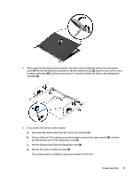
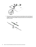
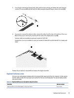
2. Lift the door up to remove it (2). Reverse this procedure to install the RJ-45 door. Display assembly To remove and disassemble the display assembly, use these procedures and illustrations. Full hinge-up displays are not available as spare parts. Spare parts for displays are available only at the subcomponent level. Before removing the display panel, follow these steps: NOTE: Make sure the display assembly panel has been separated from the base enclosure. (See Display assembly panel on page 43). 1. Prepare the computer for disassembly (see Preparation for disassembly on page 33). 2. Remove the bottom cover (see Bottom cover on page 33). 3. Remove the battery (see Battery on page 34). 4. Remove the heat sink (see Heat sink on page 40). 5. Remove the fans (see Fan assembly on page 41). 6. Remove the display assembly panel (see Display assembly panel on page 43). 1. If you need to remove the display panel: IMPORTANT: After replacing the display panel assembly or the system board, it is necessary to run the service tool to have the new ambient light sensor (ALS) data written to the system BIOS. Please search for the related advisory for more information. IMPORTANT: After replacing the display panel assembly, it is necessary to reload the calibration data. Refer to Service Advisory c06640672 for details on reloading the HP Display Control Panel Color Calibration Data Reload Process. Display assembly 53
-
 1
1 -
2
-
3
-
4
-
5
-
6
-
7
-
8
-
9
-
10
-
11
-
12
-
13
-
14
-
15
-
16
-
17
-
18
-
19
-
20
-
21
-
22
-
23
-
24
-
25
-
26
-
27
-
28
-
29
-
30
-
31
-
32
-
33
-
34
-
35
-
36
-
37
-
38
-
39
-
40
-
41
-
42
-
43
-
44
-
45
-
46
-
47
-
48
-
49
-
50
-
51
-
52
-
53
-
54
-
 55
55 -
 56
56 -
 57
57 -
 58
58 -
 59
59 -
 60
60 -
 61
61 -
 62
62 -
 63
63 -
 64
64 -
 65
65 -
66
-
67
-
68
-
69
-
70
-
71
-
72
-
73
-
74
-
75
-
76
-
77
-
78
-
79
-
80
-
81
-
82
-
83
-
84
-
85
-
86
-
87
-
88
-
89
-
90
 |
 |
