HP 1000-1400 HP 1000 Notebook PC and Compaq CQ45 Notebook PC - Maintenance and - Page 107
Use a flat-bladed screw driver, to turn the processor locking screw one-half turn
 |
View all HP 1000-1400 manuals
Add to My Manuals
Save this manual to your list of manuals |
Page 107 highlights
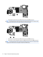
3. Disconnect the power from the computer by first unplugging the power cord from the AC outlet and then unplugging the AC adapter from the computer. 4. Remove the battery (see Battery on page 41), and then remove the following components: ● WLAN module (see WLAN module on page 49) ● Hard drive (see Hard drive on page 54) ● Keyboard (see Keyboard on page 60) ● Top cover (see Top cover on page 63) ● Speakers (see Speakers on page 71) ● USB board (see USB board on page 73) ● Power connector cable (see Power connector cable on page 75) ● Display assembly (see Display assembly on page 77) ● System board (see System board on page 86) ● Fan/heat sink assembly (see Fan/heat sink assembly on page 92) To remove the processor: 1. Use a flat-bladed screw driver (1) to turn the processor locking screw one-half turn counterclockwise (2) until you hear a click. 2. Lift the processor (3) straight up, and then remove it. NOTE: The gold triangle (4) on the processor must be aligned with the triangle icon embossed on the processor socket when you install the processor. Component replacement procedures 99
-
 1
1 -
2
-
3
-
4
-
5
-
6
-
7
-
8
-
9
-
10
-
11
-
12
-
13
-
14
-
15
-
16
-
17
-
18
-
19
-
20
-
21
-
22
-
23
-
24
-
25
-
26
-
27
-
28
-
29
-
30
-
31
-
32
-
33
-
34
-
35
-
36
-
37
-
38
-
39
-
40
-
41
-
42
-
43
-
44
-
45
-
46
-
47
-
48
-
49
-
50
-
51
-
52
-
53
-
54
-
55
-
56
-
57
-
58
-
59
-
60
-
61
-
62
-
63
-
64
-
65
-
66
-
67
-
68
-
69
-
70
-
71
-
72
-
73
-
74
-
75
-
76
-
77
-
78
-
79
-
80
-
81
-
82
-
83
-
84
-
85
-
86
-
87
-
88
-
89
-
90
-
91
-
92
-
93
-
94
-
95
-
96
-
97
-
98
-
99
-
100
-
101
-
 102
102 -
 103
103 -
 104
104 -
 105
105 -
 106
106 -
 107
107 -
 108
108 -
 109
109 -
 110
110 -
 111
111 -
 112
112 -
113
-
114
-
115
-
116
-
117
-
118
-
119
-
120
-
121
-
122
-
123
-
124
-
125
-
126
-
127
-
128
-
129
-
130
-
131
-
132
-
133
-
134
-
135
-
136
-
137
-
138
-
139
-
140
 |
 |