HP 1105 Maintenance & Service Guide HP Pro 1105 All-in-One Business PC - Page 53
Preparing to Disassemble the Computer, on Rear Cover, Memory Cover, Remove the memory cover see
 |
View all HP 1105 manuals
Add to My Manuals
Save this manual to your list of manuals |
Page 53 highlights
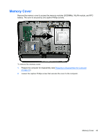
In addition, the computer supports: ● 512-Mbit, 1-Gbit, and 2-Gbit non-ECC memory technologies ● single-sided and double-sided SODIMMS ● SODIMMs constructed with x8 and x16 devices; SODIMMs constructed with x4 SDRAM are not supported NOTE: The system will not operate properly if you install unsupported SODIMMs. There are two memory sockets on the system board located behind the memory access panel. To remove or install memory modules: To remove a memory module: 1. Prepare the computer for disassembly (see Preparing to Disassemble the Computer on page 37). 2. Remove the rear cover (see Rear Cover on page 38). 3. Remove the memory cover (see Memory Cover on page 43). 4. To remove a memory module, pull outward on the latch on each side of the SODIMM (1), allow the module to lift up to about a 45-degree angle, and then pull the SODIMM out of the socket (2). The computer automatically recognizes the additional memory when you turn on the computer. 46 Chapter 7 Removal and Replacement Procedures All-in One (AIO) Chassis
-
 1
1 -
2
-
3
-
4
-
5
-
6
-
7
-
8
-
9
-
10
-
11
-
12
-
13
-
14
-
15
-
16
-
17
-
18
-
19
-
20
-
21
-
22
-
23
-
24
-
25
-
26
-
27
-
28
-
29
-
30
-
31
-
32
-
33
-
34
-
35
-
36
-
37
-
38
-
39
-
40
-
41
-
42
-
43
-
44
-
45
-
46
-
47
-
 48
48 -
 49
49 -
 50
50 -
 51
51 -
 52
52 -
 53
53 -
 54
54 -
 55
55 -
 56
56 -
 57
57 -
 58
58 -
59
-
60
-
61
-
62
-
63
-
64
-
65
-
66
-
67
-
68
-
69
-
70
-
71
-
72
-
73
-
74
-
75
-
76
-
77
-
78
-
79
-
80
-
81
-
82
-
83
-
84
-
85
-
86
-
87
-
88
-
89
-
90
-
91
-
92
-
93
-
94
-
95
-
96
-
97
-
98
-
99
-
100
-
101
-
102
-
103
-
104
-
105
-
106
-
107
-
108
-
109
-
110
-
111
-
112
-
113
-
114
-
115
-
116
-
117
-
118
-
119
-
120
-
121
-
122
-
123
-
124
-
125
-
126
-
127
-
128
-
129
-
130
-
131
-
132
-
133
-
134
-
135
-
136
-
137
-
138
-
139
-
140
-
141
-
142
-
143
-
144
-
145
-
146
-
147
-
148
-
149
 |
 |
