HP 15-bs000 Maintenance and Service Guide 1 - Page 42
and the remove it, Removal and replacement procedures for Customer Self-Repair parts
 |
View all HP 15-bs000 manuals
Add to My Manuals
Save this manual to your list of manuals |
Page 42 highlights
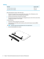
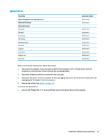
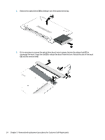
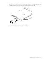
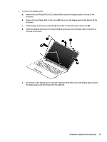
2. Remove the optical drive (2) by sliding it out of the optical drive bay. 3. If it is necessary to remove the optical drive bezel, insert a paper clip into the release hole (1) to disengage the bezel. Press the tab (2) to release the bezel from the drive. Rotate the side of the bezel (3), and the remove it (4). 34 Chapter 5 Removal and replacement procedures for Customer Self-Repair parts
-
 1
1 -
2
-
3
-
4
-
5
-
6
-
7
-
8
-
9
-
10
-
11
-
12
-
13
-
14
-
15
-
16
-
17
-
18
-
19
-
20
-
21
-
22
-
23
-
24
-
25
-
26
-
27
-
28
-
29
-
30
-
31
-
32
-
33
-
34
-
35
-
36
-
 37
37 -
 38
38 -
 39
39 -
 40
40 -
 41
41 -
 42
42 -
 43
43 -
 44
44 -
 45
45 -
 46
46 -
 47
47 -
48
-
49
-
50
-
51
-
52
-
53
-
54
-
55
-
56
-
57
-
58
-
59
-
60
-
61
-
62
-
63
-
64
-
65
-
66
-
67
-
68
-
69
-
70
-
71
-
72
-
73
-
74
-
75
-
76
-
77
-
78
-
79
-
80
-
81
-
82
-
83
-
84
-
85
-
86
-
87
-
88
-
89
-
90
-
91
-
92
-
93
-
94
-
95
-
96
-
97
-
98
-
99
-
100
-
101
-
102
-
103
-
104
-
105
-
106
-
107
-
108
-
109
-
110
-
111
-
112
-
113
-
114
-
115
-
116
 |
 |

2.
Remove the optical drive
(2)
by sliding it out of the optical drive bay.
3.
If it is necessary to remove the optical drive bezel, insert a paper clip into the release hole
(1)
to
disengage the bezel. Press the tab
(2)
to release the bezel from the drive. Rotate the side of the bezel
(3)
, and the remove it
(4)
.
34
Chapter 5
Removal and replacement procedures for Customer Self-Repair parts