HP 15-d000 HP 15 Notebook PC HP 15 TouchSmart Notebook PC Compaq 15 Notebook P - Page 106
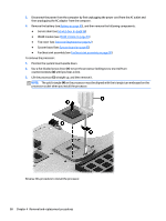
to turn the processor locking screw one-half turn, Use a flat-bladed screw driver
 |
View all HP 15-d000 manuals
Add to My Manuals
Save this manual to your list of manuals |
Page 106 highlights
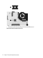
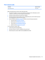
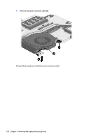
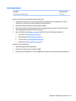
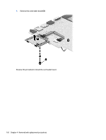
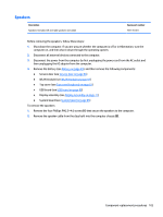
3. Disconnect the power from the computer by first unplugging the power cord from the AC outlet and then unplugging the AC adapter from the computer. 4. Remove the battery (see Battery on page 49), and then remove the following components: ● Service door (see Service door on page 56) ● WLAN module (see WLAN module on page 59) ● Top cover (see Top cover/keyboard on page 62) ● System board (see System board on page 85) ● Fan/heat sink assembly (see Fan/heat sink assembly on page 90) To remove the processor: 1. Position the system board upside down. 2. Use a flat-bladed screw driver (1) to turn the processor locking screw one-half turn counterclockwise (2) until you hear a click. 3. Lift the processor (3) straight up, and then remove it. NOTE: The gold triangle (4) on the processor must be aligned with the triangle icon embossed on the processor socket when you install the processor. Reverse this procedure to install the processor. 98 Chapter 4 Removal and replacement procedures
-
 1
1 -
2
-
3
-
4
-
5
-
6
-
7
-
8
-
9
-
10
-
11
-
12
-
13
-
14
-
15
-
16
-
17
-
18
-
19
-
20
-
21
-
22
-
23
-
24
-
25
-
26
-
27
-
28
-
29
-
30
-
31
-
32
-
33
-
34
-
35
-
36
-
37
-
38
-
39
-
40
-
41
-
42
-
43
-
44
-
45
-
46
-
47
-
48
-
49
-
50
-
51
-
52
-
53
-
54
-
55
-
56
-
57
-
58
-
59
-
60
-
61
-
62
-
63
-
64
-
65
-
66
-
67
-
68
-
69
-
70
-
71
-
72
-
73
-
74
-
75
-
76
-
77
-
78
-
79
-
80
-
81
-
82
-
83
-
84
-
85
-
86
-
87
-
88
-
89
-
90
-
91
-
92
-
93
-
94
-
95
-
96
-
97
-
98
-
99
-
100
-
 101
101 -
 102
102 -
 103
103 -
 104
104 -
 105
105 -
 106
106 -
 107
107 -
 108
108 -
 109
109 -
 110
110 -
 111
111 -
112
-
113
-
114
-
115
-
116
-
117
-
118
-
119
-
120
-
121
-
122
-
123
-
124
-
125
-
126
-
127
-
128
-
129
-
130
-
131
-
132
-
133
-
134
-
135
-
136
-
137
-
138
-
139
-
140
-
141
-
142
-
143
-
144
-
145
-
146
-
147
-
148
-
149
-
150
-
151
-
152
-
153
-
154
-
155
-
156
-
157
-
158
-
159
-
160
-
161
-
162
-
163
-
164
 |
 |