HP 15-d000 HP 15 Notebook PC HP 15 TouchSmart Notebook PC Compaq 15 Notebook P - Page 82
Flex the inside of the top edge, following image.
 |
View all HP 15-d000 manuals
Add to My Manuals
Save this manual to your list of manuals |
Page 82 highlights
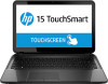
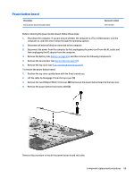
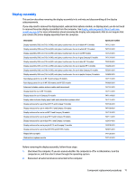
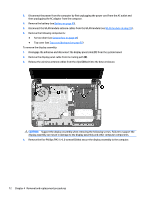
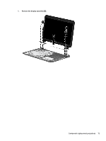
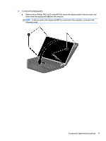
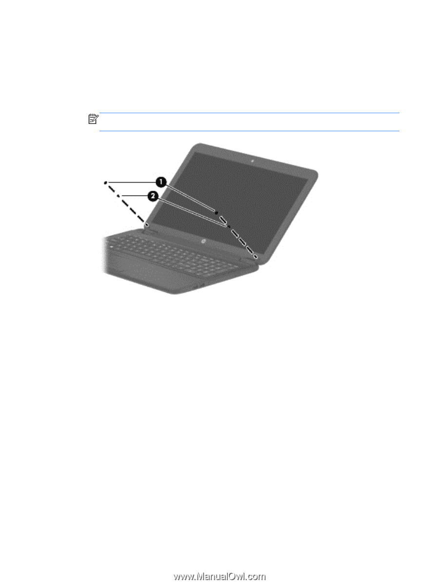
If it is necessary to replace any of the display assembly subcomponents: 1. To remove the display bezel: a. Remove the two Mylar screw covers (1) and the two Phillips PM2.5×4.5 screws (2) that secure the display bezel to the display assembly. The Mylar screw covers are included in the Rubber Kit, spare part number 747133-001 for HP 15 and Compaq 15 models, 756215-001 for HP 250 models, and 751418-001 for HP 255 models. NOTE: In this procedure, the display will NOT be connected to the computer, as shown in the following image. b. Flex the inside of the top edge (1), the left and right edges (2), and the bottom edge (3) of the display bezel until the bezel disengages from the display enclosure. 74 Chapter 4 Removal and replacement procedures
-
 1
1 -
2
-
3
-
4
-
5
-
6
-
7
-
8
-
9
-
10
-
11
-
12
-
13
-
14
-
15
-
16
-
17
-
18
-
19
-
20
-
21
-
22
-
23
-
24
-
25
-
26
-
27
-
28
-
29
-
30
-
31
-
32
-
33
-
34
-
35
-
36
-
37
-
38
-
39
-
40
-
41
-
42
-
43
-
44
-
45
-
46
-
47
-
48
-
49
-
50
-
51
-
52
-
53
-
54
-
55
-
56
-
57
-
58
-
59
-
60
-
61
-
62
-
63
-
64
-
65
-
66
-
67
-
68
-
69
-
70
-
71
-
72
-
73
-
74
-
75
-
76
-
 77
77 -
 78
78 -
 79
79 -
 80
80 -
 81
81 -
 82
82 -
 83
83 -
 84
84 -
 85
85 -
 86
86 -
 87
87 -
88
-
89
-
90
-
91
-
92
-
93
-
94
-
95
-
96
-
97
-
98
-
99
-
100
-
101
-
102
-
103
-
104
-
105
-
106
-
107
-
108
-
109
-
110
-
111
-
112
-
113
-
114
-
115
-
116
-
117
-
118
-
119
-
120
-
121
-
122
-
123
-
124
-
125
-
126
-
127
-
128
-
129
-
130
-
131
-
132
-
133
-
134
-
135
-
136
-
137
-
138
-
139
-
140
-
141
-
142
-
143
-
144
-
145
-
146
-
147
-
148
-
149
-
150
-
151
-
152
-
153
-
154
-
155
-
156
-
157
-
158
-
159
-
160
-
161
-
162
-
163
-
164
 |
 |
If it is necessary to replace any of the display assembly subcomponents:
1.
To remove the display bezel:
a.
Remove the two Mylar screw covers
(1)
and the two Phillips PM2.5×4.5 screws
(2)
that secure the
display bezel to the display assembly. The Mylar screw covers are included in the Rubber Kit, spare
part number 747133-001 for HP 15 and Compaq 15 models, 756215-001 for HP 250 models, and
751418-001 for HP 255 models.
NOTE:
In this procedure, the display will NOT be connected to the computer, as shown in the
following image.
b.
Flex the inside of the top edge
(1)
, the left and right edges
(2)
, and the bottom edge
(3)
of the
display bezel until the bezel disengages from the display enclosure.
74
Chapter 4
Removal and replacement procedures