HP 15-d000 HP 15 Notebook PC HP 15 TouchSmart Notebook PC Compaq 15 Notebook P - Page 87
microphone module, the antenna receivers, and all associated cables and hardware are transferred
 |
View all HP 15-d000 manuals
Add to My Manuals
Save this manual to your list of manuals |
Page 87 highlights
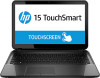
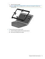
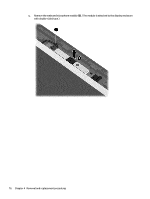
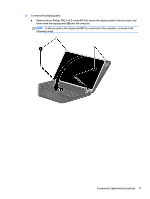
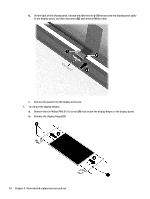
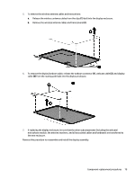
5. To remove the wireless antenna cables and transceivers: a. Release the wireless antenna cables from the clips (1) built into the display enclosure. b. Remove the wireless antenna cables and transceivers (2). 6. To remove the display/webcam cable, release the webcam connector (1), webcam cable (2), and display cable (3) from the routing path built into the display enclosure. 7. If replacing the display enclosure, be sure that the other subcomponents (including the webcam/ microphone module, the antenna receivers, and all associated cables and hardware) are transferred to the new enclosure. Reverse this procedure to reassemble and install the display assembly. Component replacement procedures 79
-
 1
1 -
2
-
3
-
4
-
5
-
6
-
7
-
8
-
9
-
10
-
11
-
12
-
13
-
14
-
15
-
16
-
17
-
18
-
19
-
20
-
21
-
22
-
23
-
24
-
25
-
26
-
27
-
28
-
29
-
30
-
31
-
32
-
33
-
34
-
35
-
36
-
37
-
38
-
39
-
40
-
41
-
42
-
43
-
44
-
45
-
46
-
47
-
48
-
49
-
50
-
51
-
52
-
53
-
54
-
55
-
56
-
57
-
58
-
59
-
60
-
61
-
62
-
63
-
64
-
65
-
66
-
67
-
68
-
69
-
70
-
71
-
72
-
73
-
74
-
75
-
76
-
77
-
78
-
79
-
80
-
81
-
 82
82 -
 83
83 -
 84
84 -
 85
85 -
 86
86 -
 87
87 -
 88
88 -
 89
89 -
 90
90 -
 91
91 -
 92
92 -
93
-
94
-
95
-
96
-
97
-
98
-
99
-
100
-
101
-
102
-
103
-
104
-
105
-
106
-
107
-
108
-
109
-
110
-
111
-
112
-
113
-
114
-
115
-
116
-
117
-
118
-
119
-
120
-
121
-
122
-
123
-
124
-
125
-
126
-
127
-
128
-
129
-
130
-
131
-
132
-
133
-
134
-
135
-
136
-
137
-
138
-
139
-
140
-
141
-
142
-
143
-
144
-
145
-
146
-
147
-
148
-
149
-
150
-
151
-
152
-
153
-
154
-
155
-
156
-
157
-
158
-
159
-
160
-
161
-
162
-
163
-
164
 |
 |
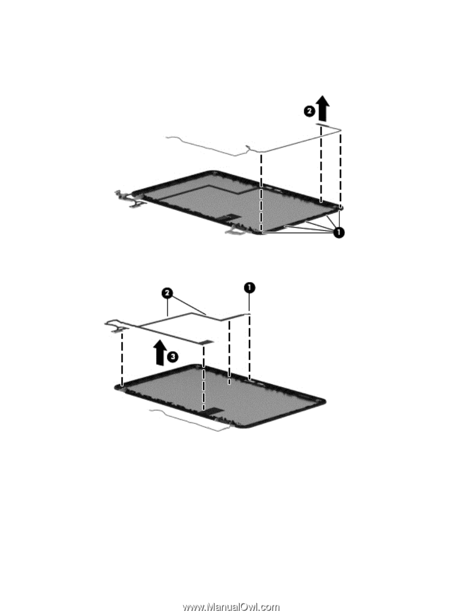
5.
To remove the wireless antenna cables and transceivers:
a.
Release the wireless antenna cables from the clips
(1)
built into the display enclosure.
b.
Remove the wireless antenna cables and transceivers
(2)
.
6.
To remove the display/webcam cable, release the webcam connector
(1)
, webcam cable
(2)
, and display
cable
(3)
from the routing path built into the display enclosure.
7.
If replacing the display enclosure, be sure that the other subcomponents (including the webcam/
microphone module, the antenna receivers, and all associated cables and hardware) are transferred to
the new enclosure.
Reverse this procedure to reassemble and install the display assembly.
Component replacement procedures
79