HP 15-r029wm HP 15 Notebook PC Compaq 15 Notebook PC Maintenance and Service G - Page 51
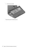
Lift the rear edge of the top cover, until it disengage from the base enclosure.
 |
View all HP 15-r029wm manuals
Add to My Manuals
Save this manual to your list of manuals |
Page 51 highlights
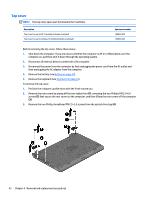
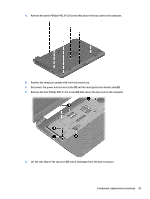
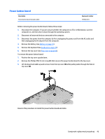
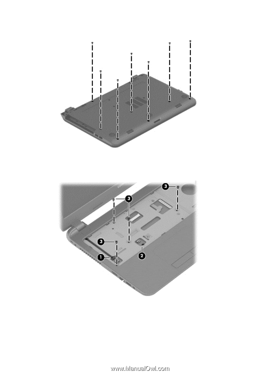
4. Remove the seven Phillips PM2.5×5.0 screws that secure the top cover to the computer. 5. Position the computer upright with the front toward you. 6. Disconnect the power button board cable (1) and the touchpad button board cable (2). 7. Remove the four Phillips PM2.5×5.0 screws (3) that secure the top cover to the computer. 8. Lift the rear edge of the top cover (1) until it disengage from the base enclosure. Component replacement procedures 43
-
 1
1 -
2
-
3
-
4
-
5
-
6
-
7
-
8
-
9
-
10
-
11
-
12
-
13
-
14
-
15
-
16
-
17
-
18
-
19
-
20
-
21
-
22
-
23
-
24
-
25
-
26
-
27
-
28
-
29
-
30
-
31
-
32
-
33
-
34
-
35
-
36
-
37
-
38
-
39
-
40
-
41
-
42
-
43
-
44
-
45
-
 46
46 -
 47
47 -
 48
48 -
 49
49 -
 50
50 -
 51
51 -
 52
52 -
 53
53 -
 54
54 -
 55
55 -
 56
56 -
57
-
58
-
59
-
60
-
61
-
62
-
63
-
64
-
65
-
66
-
67
-
68
-
69
-
70
-
71
-
72
-
73
-
74
-
75
-
76
-
77
-
78
-
79
-
80
-
81
-
82
-
83
-
84
-
85
-
86
-
87
-
88
-
89
-
90
-
91
-
92
-
93
-
94
-
95
-
96
-
97
-
98
-
99
-
100
-
101
-
102
-
103
-
104
-
105
-
106
-
107
-
108
-
109
-
110
-
111
-
112
-
113
-
114
-
115
-
116
-
117
-
118
-
119
-
120
-
121
-
122
 |
 |
4.
Remove the seven Phillips PM2.5×5.0 screws that secure the top cover to the computer.
5.
Position the computer upright with the front toward you.
6.
Disconnect the power button board cable
(1)
and the touchpad button board cable
(2)
.
7.
Remove the four Phillips PM2.5×5.0 screws
(3)
that secure the top cover to the computer.
8.
Lift the rear edge of the top cover
(1)
until it disengage from the base enclosure.
Component replacement procedures
43