HP 15-r029wm HP 15 Notebook PC Compaq 15 Notebook PC Maintenance and Service G - Page 65
disengage the connectors from the side of the base enclosure
 |
View all HP 15-r029wm manuals
Add to My Manuals
Save this manual to your list of manuals |
Page 65 highlights
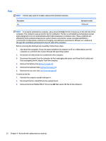
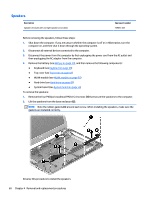
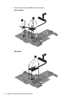
(4): Display cable 2. Remove the two Phillips PM2.5×5.0 screws (5) that secure the system board to the computer. 3. Lift the right side of the system board (1), and then pull the board away from the computer enough to disengage the connectors from the side of the base enclosure (2). NOTE: Be careful not to inadvertently disconnect the speaker cable when lifting the system board. 4. Flip the system board upside down to gain access to the speaker connector (1). Component replacement procedures 57
-
 1
1 -
2
-
3
-
4
-
5
-
6
-
7
-
8
-
9
-
10
-
11
-
12
-
13
-
14
-
15
-
16
-
17
-
18
-
19
-
20
-
21
-
22
-
23
-
24
-
25
-
26
-
27
-
28
-
29
-
30
-
31
-
32
-
33
-
34
-
35
-
36
-
37
-
38
-
39
-
40
-
41
-
42
-
43
-
44
-
45
-
46
-
47
-
48
-
49
-
50
-
51
-
52
-
53
-
54
-
55
-
56
-
57
-
58
-
59
-
 60
60 -
 61
61 -
 62
62 -
 63
63 -
 64
64 -
 65
65 -
 66
66 -
 67
67 -
 68
68 -
 69
69 -
 70
70 -
71
-
72
-
73
-
74
-
75
-
76
-
77
-
78
-
79
-
80
-
81
-
82
-
83
-
84
-
85
-
86
-
87
-
88
-
89
-
90
-
91
-
92
-
93
-
94
-
95
-
96
-
97
-
98
-
99
-
100
-
101
-
102
-
103
-
104
-
105
-
106
-
107
-
108
-
109
-
110
-
111
-
112
-
113
-
114
-
115
-
116
-
117
-
118
-
119
-
120
-
121
-
122
 |
 |

(4)
: Display cable
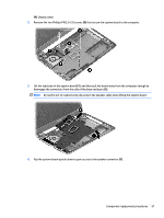
2.
Remove the two Phillips PM2.5×5.0 screws
(5)
that secure the system board to the computer.
3.
Lift the right side of the system board
(1)
, and then pull the board away from the computer enough to
disengage the connectors from the side of the base enclosure
(2)
.
NOTE:
Be careful not to inadvertently disconnect the speaker cable when lifting the system board.
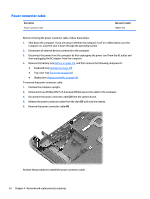
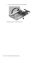
4.
Flip the system board upside down to gain access to the speaker connector
(1)
.
Component replacement procedures
57