HP 17.3kVA HP Monitored Power Distribution Unit User Guide - Page 38
Front Panel Ports, Status Indicators, and Operation Buttons
 |
View all HP 17.3kVA manuals
Add to My Manuals
Save this manual to your list of manuals |
Page 38 highlights
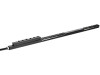
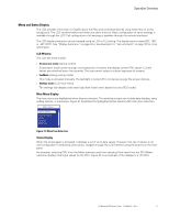
Operation Overview Main Menu AAcCtivTeIVAlEarAmLsARMS AMEOleaVUtremETrNssLHTEiTsLtOoRrEGy ADINGSEnter SSeEttTinTgsINGS ESC PeDPUDIUnfoINFO Meter PDU Sections Environment PDU Meter Total Input Enter ESC Total Input Total Input .Frequency Active Power Down 50.23 Hz Down 100 W ESC Total Input Peak Power of xxxx W since 07/01/2011 17:32:23 Total Input Energy Down 16.238 kWh Down since 07/01/2011 17:32:23 Total Input Power Factor 0.912 Down Total Input Apparent Power 120 VA Down Reactive Power 20 VAR Figure 22. Example of Selected Value Display Front Panel Ports, Status Indicators, and Operation Buttons The Monitored PDU front panel includes communication and environmental monitoring ports, LED status indicators, and operation buttons. There are three different front panel versions. Although the button and port position varies, you can recognize the same button and port design from model to model (see Figure 23). 1 2 3 4 5 6 15 14 13 12 11 10 9 8 7 Figure 23. Front Panel Ports and Buttons (22U, 36U, and 42U Front Panel) Table 5 describes the ports and buttons identified in Figure 23. Table 5. Communication and Environmental Monitoring Ports Reference Number Description 1 Service or Serial Port (Settings/Sensor) 2 Yellow Serial Service Port LED: RS-232 Operation and Activity Status OFF: Normal operation FLASHING: Communicating with EMP (if installed) 3 Green Serial Service Port LED: PDU Communication Status OFF: PDU start-up in progress FLASHING: Normal operation (network communication module operational) 4 USB Port (Reserved for Future Use) 5 Backward (Down) Scroll Button 6 Escape (ESC) Button 7 Enter Key 8 Forward (Up) Scroll Button HP Monitored PDU User's Guide P-164000281-Rev 1 32
-
 1
1 -
2
-
3
-
4
-
5
-
6
-
7
-
8
-
9
-
10
-
11
-
12
-
13
-
14
-
15
-
16
-
17
-
18
-
19
-
20
-
21
-
22
-
23
-
24
-
25
-
26
-
27
-
28
-
29
-
30
-
31
-
32
-
 33
33 -
 34
34 -
 35
35 -
 36
36 -
 37
37 -
 38
38 -
 39
39 -
 40
40 -
 41
41 -
 42
42 -
 43
43 -
44
-
45
-
46
-
47
-
48
-
49
-
50
-
51
-
52
-
53
-
54
-
55
-
56
-
57
-
58
-
59
-
60
-
61
-
62
-
63
-
64
-
65
-
66
-
67
-
68
-
69
-
70
-
71
-
72
-
73
-
74
-
75
-
76
-
77
-
78
-
79
-
80
-
81
-
82
-
83
-
84
-
85
-
86
-
87
-
88
-
89
-
90
-
91
-
92
-
93
-
94
-
95
-
96
-
97
-
98
-
99
-
100
-
101
-
102
-
103
-
104
-
105
-
106
-
107
-
108
-
109
-
110
-
111
-
112
-
113
-
114
-
115
-
116
-
117
-
118
-
119
-
120
 |
 |
