HP 3020 Cisco Catalyst Blade Switch 3020 for HP Getting Started Guide - Page 3
Installing the Switch Module in the Blade Server - review
 |
UPC - 882658086625
View all HP 3020 manuals
Add to My Manuals
Save this manual to your list of manuals |
Page 3 highlights
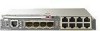
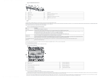
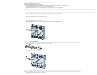
Cisco Catalyst Blade Switch 3020 for HP Getting Started Guide [Cisco Catalyst Blade Switch 3000 Series] - Cisco Systems • See the HP c-Class documentation for information on the port mapping between blade servers and the switch modules. 4 Installing the Switch Module in the Blade Server Before you install the switch module in the blade server, consider these points: • Review and become familiar with the safety guidelines in the Regulatory Compliance and Safety Information for the Cisco Catalyst Blade Switch 3020 for HP that accompanies this guide. • Review and become familiar with the safety guidelines in the HP BladeSystem enclosure setup and installation guide. • Review and become familiar with the temperature, power, and grounding requirements specified in the HP BladeSystem enclosure setup and installation guide. Warning Only trained and qualified personnel should be allowed to install, replace, or service this equipment. Statement 1030 Caution To prevent electrostatic-discharge (ESD) damage when installing switch modules, follow your normal board and component handling procedures. Note When you install a switch module, you do not need to power down the blade server. Follow these steps to install the switch module in the blade server: Step 1 If you have not already done so, touch the static-protective package that contains the switch module to an unpainted metal part of the blade server for at least 2 seconds. Step 2 Remove the switch module from its static-protective package. Step 3 Remove the interconnect blank from the bay where you plan to install the switch module, if one is present, and install the switch module. (See Figure 3.) Figure 3 Removing the Interconnect Module Blank from the Blade Server 1 Lever for the interconnect module blank Step 4 Ensure that the release latch on the switch module is in the open position (perpendicular to the module): Step 5 Slide the switch module into the bay until it stops. (See Figure 4.) Figure 4 Installing the Switch Module into the Blade Server Interconnect Module Bay 1 Switch module release latch http://www.cisco.com/en/US/products/ps6748/products_getting_started_guide09186a00806c38a8.html (3 of 11)4/19/2007 10:27:48 AM Step 6 Push the release latch on the front of the switch module to the closed position.
-
 1
1 -
 2
2 -
 3
3 -
 4
4 -
 5
5 -
 6
6 -
 7
7 -
 8
8 -
 9
9 -
10
-
11
 |
 |
