HP 3020 Cisco Catalyst Blade Switch 3020 for HP Getting Started Guide - Page 7
Completing the Express Setup Fields, Refreshing the PC IP Address, Using the Device Manager
 |
UPC - 882658086625
View all HP 3020 manuals
Add to My Manuals
Save this manual to your list of manuals |
Page 7 highlights
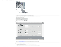
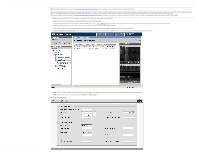
Cisco Catalyst Blade Switch 3020 for HP Getting Started Guide [Cisco Catalyst Blade Switch 3000 Series] - Cisco Systems Step 8 Go to "Completing the Express Setup Fields" section to finish setting up the switch module using the Express Setup screen of the Device Manager. Completing the Express Setup Fields Follow these steps to finish setting up the switch module: Step 1 Enter this information in the Network Settings fields: - In the Management Interface (VLAN ID) field, the default is 1. Enter a new VLAN ID only if you want to change the management interface through which you manage the switch module and to which you assign IP information. The VLAN ID range is 1 to 1001. - In the IP Address field, enter the IP address of the switch module. In the IP Subnet Mask field, click the drop-down arrow, and select an IP Subnet Mask. - In the Default Gateway field, enter the IP address for the default gateway (router). - Enter your password in the Switch Password field. The password can be from 1 to 25 alphanumeric characters, can start with a number, is case sensitive, allows embedded spaces, but does not allow spaces at the beginning or end. In the Confirm Switch Password field, enter your password again. Step 2 (Optional) You can enter the Optional Settings information now or enter it later by using the device manager interface: - In the Host Name field, enter a name for the switch module. The host name is limited to 31 characters; embedded spaces are not allowed. - In the System Contact field, enter the name of the person who is responsible for the switch module. In the System Location field, enter the wiring closet, floor, or building where the switch module is located. - In the Telnet Access field, click Enable if you are going to use Telnet to manage the switch module by using the CLI. If you enable Telnet access, you must enter a Telnet password. - In the Telnet Password field, enter a password. The Telnet password can be from 1 to 25 alphanumeric characters, is case sensitive, allows embedded spaces, but does not allow spaces at the beginning or end. In the Confirm Telnet Password field, re-enter the Telnet password. - In the SNMP field, click Enable to enable Simple Network Management Protocol (SNMP). Enable SNMP only if you plan to manage switches by using CiscoWorks 2000 or another SNMP-based network-management system. If you enable SNMP, you must enter a community string in the SNMP Read Community field, the SNMP Write Community field, or both. SNMP community strings authenticate access to MIB objects. Embedded spaces are not allowed in SNMP community strings. When you set the SNMP read community, you can access SNMP information, but you cannot modify it. When you set the SNMP write community, you can both access and modify SNMP information. Step 3 Click Submit to save your settings, or click Cancel to clear your settings. When you click Submit, the switch module is configured and exits Express Setup mode. The PC displays a warning message and then attempts to connect with the new switch module IP address. If you configured the switch module with an IP address that is in a different subnet from the PC, connectivity between the PC and the switch module is lost. Step 4 Disconnect the switch module from the PC, and install the switch module in your network. See the "Managing the Switch Module" section for information about configuring and managing the switch module. If you need to rerun Express Setup, see the "Resetting the Switch Module" section. To install additional switch modules, repeat the steps in the "Installing the Switch Module in the Blade Server" section through the "Running Express Setup" section. Refreshing the PC IP Address After you complete Express Setup, you should refresh the PC IP address: • For a dynamically assigned IP address, disconnect the PC from the switch module, and reconnect the PC to the network. The network DHCP server assigns a new IP address to the PC. • For a statically assigned IP address, change it to the previously configured IP address. 6 Managing the Switch Module After you complete Express Setup and install the switch module in your network, use the device manager or other management options described in this section for further configuration. Using the Device Manager The simplest way to manage the switch module is by using the device manager that is in the switch module memory. This is a web interface that offers quick configuration and monitoring. You can access the device manager from anywhere in your network through a web browser. Follow these steps: 1. Launch a web browser on your PC or workstation. 2. Enter the switch module IP address in the web browser, and press Enter. The device manager page appears. http://www.cisco.com/en/US/products/ps6748/products_getting_started_guide09186a00806c38a8.html (7 of 11)4/19/2007 10:27:48 AM 3. Use the device manager to perform basic switch module configuration and monitoring. Refer to the device manager online help for more information.
-
 1
1 -
 2
2 -
 3
3 -
 4
4 -
 5
5 -
 6
6 -
 7
7 -
 8
8 -
 9
9 -
 10
10 -
 11
11
 |
 |
