HP 3115m HP 3115m Notebook PC - Maintenance and Service Guide
HP 3115m Manual
 |
View all HP 3115m manuals
Add to My Manuals
Save this manual to your list of manuals |
HP 3115m manual content summary:
- HP 3115m | HP 3115m Notebook PC - Maintenance and Service Guide - Page 1
HP 3115m Notebook PC Maintenance and Service Guide - HP 3115m | HP 3115m Notebook PC - Maintenance and Service Guide - Page 2
in the express warranty statements accompanying such products and services. Nothing herein should be construed as constituting an additional warranty. HP shall not be liable for technical or editorial errors or omissions contained herein. First Edition: November 2011 Document Part Number: 667975-001 - HP 3115m | HP 3115m Notebook PC - Maintenance and Service Guide - Page 3
adjoining optional printer, or a soft surface, such as pillows or rugs or clothing, to block airflow. Also, do not allow the AC adapter to contact the skin or a soft surface, such as pillows or rugs or clothing, during operation. The device and the AC adapter comply with the user-accessible surface - HP 3115m | HP 3115m Notebook PC - Maintenance and Service Guide - Page 4
iv Safety warning notice - HP 3115m | HP 3115m Notebook PC - Maintenance and Service Guide - Page 5
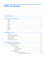
of contents 1 Product description ...1 2 External component identification 4 Display ...5 Buttons ...6 Keys ...8 Lights ...9 TouchPad ...10 Front ...10 Left side ...11 Right side ...12 Bottom ...13 3 Illustrated parts catalog 14 Service tag ...15 Computer major components 16 Display assembly - HP 3115m | HP 3115m Notebook PC - Maintenance and Service Guide - Page 6
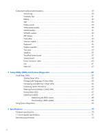
...37 WWAN module ...39 RTC battery ...41 Hard drive ...43 Memory module ...45 Keyboard ...46 Display assembly ...49 Top cover ...53 Speakers ...55 TouchPad button board 57 System board ...58 Power connector cable 60 Fan ...61 Heat sink ...63 5 Setup Utility (BIOS) and System Diagnostics 65 Using - HP 3115m | HP 3115m Notebook PC - Maintenance and Service Guide - Page 7
restore media 76 Changing the computer boot order 76 Backing up and recovering your information 77 Using Windows Backup and Restore 78 Using Windows system restore points 78 When to create restore points 78 Create a system restore point 79 Restore to a previous date and time 79 8 Power cord - HP 3115m | HP 3115m Notebook PC - Maintenance and Service Guide - Page 8
viii - HP 3115m | HP 3115m Notebook PC - Maintenance and Service Guide - Page 9
Processors Chipset Graphics Panel Memory Hard drives Description HP 3115m Notebook PC AMD® E450 1.65-GHz processor (1.0-MB L2 cache, 1333-MHz, dual core, 18 W) AMD E300 1.30-GHz processor (1.0-MB L2 cache, 1066-MHz, dual core, 18 W) AMD A50M fusion controller hub (FCH) AMD Radeon™ HD 6320 discrete - HP 3115m | HP 3115m Notebook PC - Maintenance and Service Guide - Page 10
-Layer Combo Drive Audio and video Single digital microphone Beats Audio with Beats logo (support Beats hotkey [fn+b]) Two integrated stereo speakers HP TrueVision high-definition webcam (fixed, no tilt, 1280×800 by 30 frames per second) Ethernet Integrated Gigabit network interface card - HP 3115m | HP 3115m Notebook PC - Maintenance and Service Guide - Page 11
7 Professional (64- and 32-bit) ● Windows 7 Starter 32-bit (only on computer models equipped with 2-GB memory) ● DVD SSRD recovery solution Serviceability End-user replaceable parts: ● AC adapter ● Battery ● Hard drive ● Memory modules (2) ● SIM ● Solid-state drive ● WLAN module ● WWAN module 3 - HP 3115m | HP 3115m Notebook PC - Maintenance and Service Guide - Page 12
2 External component identification 4 Chapter 2 External component identification - HP 3115m | HP 3115m Notebook PC - Maintenance and Service Guide - Page 13
off the display or initiates Sleep if the display is closed while the power is on. NOTE: The display switch is not visible from the outside of the computer. (2) WLAN antennas (2)* Send and receive wireless signals to communicate with WLANs. (3) WWAN antennas (2)* (select models only) Send and - HP 3115m | HP 3115m Notebook PC - Maintenance and Service Guide - Page 14
Buttons 6 Chapter 2 External component identification - HP 3115m | HP 3115m Notebook PC - Maintenance and Service Guide - Page 15
to turn off the computer. To learn more about your power settings, select Start > Control Panel > System and Security > Power Options, or refer to the HP Notebook Reference Guide. ● When the computer is off or in Hibernation, press the button to open HP QuickWeb. ● When the computer is in Microsoft - HP 3115m | HP 3115m Notebook PC - Maintenance and Service Guide - Page 16
when pressed in combination with the fn key. Displays system information when pressed in combination with the esc key. Displays the Windows Start menu. Displays a shortcut menu for items beneath the pointer. Execute frequently used system functions. 8 Chapter 2 External component identification - HP 3115m | HP 3115m Notebook PC - Maintenance and Service Guide - Page 17
(1) (2) (3) (4) (5) Component Power light Mute light Wireless light Caps lock light TouchPad light Description Off: Computer sound is on. ● White: An integrated wireless device, such as a WLAN device and/or a Bluetooth device, is on. ● Amber: All wireless devices are off. On: Caps lock is on. ● - HP 3115m | HP 3115m Notebook PC - Maintenance and Service Guide - Page 18
on and off. Quickly double-tap the TouchPad on/off button to turn the TouchPad on and off. Moves the pointer and selects or activates items on the screen. Functions like the left button on an external mouse. Functions like the right button on an external mouse. Description Produce sound. 10 Chapter - HP 3115m | HP 3115m Notebook PC - Maintenance and Service Guide - Page 19
the hard drive. NOTE: For information on HP ProtectSmart Hard Drive Protection, refer to the HP Notebook Reference Guide. Connects an optional video or audio device, such as a high-definition television, or any compatible digital or audio component. Connects an optional USB device. Left side 11 - HP 3115m | HP 3115m Notebook PC - Maintenance and Service Guide - Page 20
monitor port (6) RJ-45 (network) jack Description Supports the following digital card formats: ● MultiMediaCard ● SD Card ● Secure Digital High-Capacity (SDHC) Card ● Secure Digital Extended Capacity (SDxC) Card Produce sound when connected to optional powered stereo speakers, headphones, ear - HP 3115m | HP 3115m Notebook PC - Maintenance and Service Guide - Page 21
SIM slot (select models only) Battery/service cover latch Vent Service cover Description Holds the battery. Supports a wireless subscriber identity module (SIM). The SIM slot is located inside the battery bay. Releases the battery from the battery bay. Enables airflow to cool internal components - HP 3115m | HP 3115m Notebook PC - Maintenance and Service Guide - Page 22
3 Illustrated parts catalog 14 Chapter 3 Illustrated parts catalog - HP 3115m | HP 3115m Notebook PC - Maintenance and Service Guide - Page 23
components. The part number helps a service technician to determine what components and parts are needed. This number describes the duration of the warranty period for the computer. This is the alphanumeric identifier used to locate documents, drivers, and support for the computer. Service tag 15 - HP 3115m | HP 3115m Notebook PC - Maintenance and Service Guide - Page 24
Computer major components 16 Chapter 3 Illustrated parts catalog - HP 3115m | HP 3115m Notebook PC - Maintenance and Service Guide - Page 25
632155-001 Ralink 3592BC8 802.11a/b/g/n 2×2 WiFi and Bluetooth 3.0+HS Combo Adapter 630813-001 Hard drive (does not include the hard drive bracket, connector cable, isolators, or screws. These components are included in the Hard Drive Hardware Kit, spare part number 664913-001): 500-GB, 5400 - HP 3115m | HP 3115m Notebook PC - Maintenance and Service Guide - Page 26
storage devices on page 21 for more Hard Drive Hardware Kit information. Service cover in charcoal finish (includes two rubber feet and shielding): Rubber Kit (includes two rear corner covers and two rubber feet) 6-cell, 55-Whr, 2.55-Ah Li-ion battery Spare part number 645193-001 659933-001 675097 - HP 3115m | HP 3115m Notebook PC - Maintenance and Service Guide - Page 27
Item (1) (2) (3a) (3b) (4) Component Display bezel (includes display lid switch magnet) Webcamera module Display Hinge Kit,includes: Left and right hinges Left and right hinge brackets 11.6-in, LED, HD, BrightView SVA display panel Spare part number 669025-001 659516-001 659499-001 668353-001 - HP 3115m | HP 3115m Notebook PC - Maintenance and Service Guide - Page 28
Item (5) (6) (7) Component Spare part number Display Cable Kit (includes display panel cable and webcamera module cable) 659498-001 Wireless Antenna Kit (includes left and right WLAN antenna cables and transceivers and left and right WWAN antenna cables and transceivers) 659492-001 Display - HP 3115m | HP 3115m Notebook PC - Maintenance and Service Guide - Page 29
(3a) (3b) (3c) Component Spare part number Hard drive (does not include the hard drive bracket, connector cable, isolators, or screws): 500-GB, 5400-rpm, SATA, 7.0-mm 669299-001 320-GB, 5400-rpm, SATA, 7.0-mm 645193-001 Solid-state drive: 160-GB solid-state drive 659933-001 128-GB solid - HP 3115m | HP 3115m Notebook PC - Maintenance and Service Guide - Page 30
-Layer Combo Drive Miscellaneous parts Component 65-W PFC RC V 3-wire HP Smart AC adapter HP lock: HP keyed cable lock HP notebook combination lock HP USB optical mouse Power cord (3-pin, black, 1.83-m): For use in Argentina For use in Brazil For use in North America Screw Kit Spare part number - HP 3115m | HP 3115m Notebook PC - Maintenance and Service Guide - Page 31
Spare part number Description 434594-001 HP USB optical mouse 490371-001 Power cord for use in North America (3-pin, black, 1.83-m) 490371-202 Power cord for use in Brazil (3-pin, black, 1.83-m) 490371-D01 Power cord for use in Argentina (3-pin, black, 1.83-m) 591699-001 HP notebook - HP 3115m | HP 3115m Notebook PC - Maintenance and Service Guide - Page 32
two rear corner covers and two rubber feet) 664999-001 Heat sink (includes replacement thermal material) 665000-001 Fan 668353-001 11.6-in, LED, HD, BrightView SVA display panel 669025-001 Display bezel (includes display lid switch magnet) 669299-001 500-GB, 5400-rpm hard drive only (does - HP 3115m | HP 3115m Notebook PC - Maintenance and Service Guide - Page 33
work area to prevent damage. Plastic parts CAUTION: Using excessive force during disassembly and reassembly can damage plastic parts. Use care when handling the plastic parts. Apply pressure only at the points designated in the maintenance instructions. Cables and connectors CAUTION: When servicing - HP 3115m | HP 3115m Notebook PC - Maintenance and Service Guide - Page 34
disc is not in the drive and be sure that the optical drive tray is closed. Handle drives on surfaces covered with at least one inch of shock-proof foam. Avoid dropping drives from any height onto any surface. After removing a hard drive, an optical drive, or a diskette drive, place it in a static - HP 3115m | HP 3115m Notebook PC - Maintenance and Service Guide - Page 35
electrostatic-safe containers until you are ready to install them. Before touching an electronic component, discharge Relative humidity 10% 40% 35,000 V 15,000 V 12,000 V 5,000 V 6,000 V 800 V 2,000 V 700 V 11,500 V 4,000 V 14,500 V 5,000 V 26,500 V 20,000 V 21,000 V 11,000 V 55 - HP 3115m | HP 3115m Notebook PC - Maintenance and Service Guide - Page 36
work area free of nonconductive materials, such as ordinary plastic assembly aids and Styrofoam. ● Handle ESD-sensitive components, parts, and assemblies by the case or PCM laminate. Handle these items only at static-free workstations. ● Avoid contact with pins, leads, or circuitry. ● Turn off power - HP 3115m | HP 3115m Notebook PC - Maintenance and Service Guide - Page 37
, aprons, and sleeve protectors ● Conductive bins and other assembly or soldering aids ● Nonconductive foam ● Conductive tabletop workstations with ground cords of one megohm resistance ● Static-dissipative tables or floor mats with hard ties to the ground ● Field service kits ● Static awareness - HP 3115m | HP 3115m Notebook PC - Maintenance and Service Guide - Page 38
and location during removal and replacement. Service tag When ordering parts or requesting information, provide the computer serial number and model number provided on the service tag. The battery must be removed to access the service tag. See Battery on page 32 for battery removal procedures. Item - HP 3115m | HP 3115m Notebook PC - Maintenance and Service Guide - Page 39
documents, drivers, and support for the computer. Computer feet The computer feet are adhesive-backed rubber pads. There are 2 oblong rubber feet that attach to the rear corner covers as indicated in the following illustration. These feet are available in the Rubber Kit, spare part number 664996 - HP 3115m | HP 3115m Notebook PC - Maintenance and Service Guide - Page 40
by first unplugging the power cord from the AC outlet and then unplugging the AC adapter from the computer. Remove the battery: 1. Slide the battery/service cover latch (1) to release the battery. 2. Pivot the front edge of the battery (2) up and back. 3. Remove the battery from the computer. To - HP 3115m | HP 3115m Notebook PC - Maintenance and Service Guide - Page 41
. 2. Disconnect all external devices connected to the computer. 3. Disconnect the power from the computer by first unplugging the power cord from the AC outlet and then unplugging the AC adapter from the computer. 4. Remove the battery (see Battery on page 32). Remove the SIM: 1. Press in on the SIM - HP 3115m | HP 3115m Notebook PC - Maintenance and Service Guide - Page 42
panel Description 11.6-in, LED, HD, BrightView SVA display panel Spare part number 668353- power from the computer by first unplugging the power cord from the AC outlet and then unplugging the AC adapter from the computer. 4. Remove the battery (see Battery on page 32). 5. Remove the service cover - HP 3115m | HP 3115m Notebook PC - Maintenance and Service Guide - Page 43
unplugging the power cord from the AC outlet and then unplugging the AC adapter from the computer. 4. Remove the battery (see Battery on page 32). 5. Remove the display bezel (see Display panel on page 34). 6. Remove the display panel (see Display panel on page 34). Component replacement procedures - HP 3115m | HP 3115m Notebook PC - Maintenance and Service Guide - Page 44
to the display enclosure with double-sided tape) 2. Disconnect the webcamera module cable (2) from the webcamera module. 3. Remove the webcamera module. Reverse this procedure to install the webcamera module. 36 Chapter 4 Removal and - HP 3115m | HP 3115m Notebook PC - Maintenance and Service Guide - Page 45
the power cord from the AC outlet and then unplugging the AC adapter from the computer. 4. Remove the battery (see Battery on page 32). Remove the WLAN module: 1. Firmly slide and hold the battery/service cover latch (1) to the left to release the service cover, and then slide the service cover - HP 3115m | HP 3115m Notebook PC - Maintenance and Service Guide - Page 46
3. Remove the service cover. The service cover is available using spare part number 659503-001. 4. Disconnect the WLAN antenna cables into the memory module slot. NOTE: If the WLAN antennas are not connected to the terminals on the WLAN module, the protective sleeves must be installed on the antenna - HP 3115m | HP 3115m Notebook PC - Maintenance and Service Guide - Page 47
devices connected to the computer. 3. Disconnect the power from the computer by first unplugging the power cord from the AC outlet and then unplugging the AC adapter from the computer. 4. Remove the battery (see Battery on page 32). 5. Remove the service cover (see WLAN module on page 37). Remove - HP 3115m | HP 3115m Notebook PC - Maintenance and Service Guide - Page 48
modules are designed with a notch (4) to prevent incorrect insertion into the memory module slot. NOTE: If the WWAN antennas are not connected to the terminals on the WWAN module, the protective sleeves must be installed on the antenna connectors, as shown in the following illustration. Reverse this - HP 3115m | HP 3115m Notebook PC - Maintenance and Service Guide - Page 49
compatibility Spare part number 664994-001 599516-001 Before removing the RTC battery, power cord from the AC outlet and then unplugging the AC adapter from the computer. 4. Remove the battery (see Battery on page 32). 5. Remove the service cover (see WLAN module on page 37). Remove the RTC battery - HP 3115m | HP 3115m Notebook PC - Maintenance and Service Guide - Page 50
WWAN capability. 3. Use a thin, non-conductive tool to remove the RTC battery from the socket on the system board. Reverse this procedure to install the RTC battery on computer models with WLAN capability. When installing the RTC battery, make sure the "+" sign faces up. 42 Chapter 4 Removal and - HP 3115m | HP 3115m Notebook PC - Maintenance and Service Guide - Page 51
by first unplugging the power cord from the AC outlet and then unplugging the AC adapter from the computer. 4. Remove the battery (see Battery on page 32). 5. Remove the service cover (see WLAN module on page 37). Remove the hard drive: 1. Disconnect the hard drive connector cable (1) from the - HP 3115m | HP 3115m Notebook PC - Maintenance and Service Guide - Page 52
(2), the bracket (3), or the isolators (4), remove and replace the components. The bracket, connector cable, isolators, and screws are available in the Hard Drive Hardware Kit, spare part number 664913-001. Reverse this procedure to reassemble and install the hard drive. 44 Chapter 4 Removal and - HP 3115m | HP 3115m Notebook PC - Maintenance and Service Guide - Page 53
from the computer by first unplugging the power cord from the AC outlet and then unplugging the AC adapter from the computer. 4. Remove the battery (see Battery on page 32). 5. Remove the service cover (see WLAN module on page 37). Remove the memory module: 1. Spread the retaining tabs (1) on each - HP 3115m | HP 3115m Notebook PC - Maintenance and Service Guide - Page 54
from the computer by first unplugging the power cord from the AC outlet and then unplugging the AC adapter from the computer. 4. Remove the battery (see Battery on page 32). 5. Remove the service cover (see WLAN module on page 37). Remove the keyboard: 1. Remove the two rubber feet (1) that are - HP 3115m | HP 3115m Notebook PC - Maintenance and Service Guide - Page 55
computer. 5. Rest and secure the computer on its right side. 6. Partially open the computer. 7. Insert a screwdriver or similar thin tool into the keyboard release opening, and then press on the back of the keyboard until the keyboard disengages from the computer. Component replacement procedures 47 - HP 3115m | HP 3115m Notebook PC - Maintenance and Service Guide - Page 56
palm rest. 10. Release the zero insertion force (ZIF) connector (2) to which the keyboard cable is attached, and then disconnect the keyboard cable (3) from the system board. 11. Remove the keyboard (3). Reverse this procedure to install the keyboard. 48 Chapter 4 Removal and replacement procedures - HP 3115m | HP 3115m Notebook PC - Maintenance and Service Guide - Page 57
the computer by first unplugging the power cord from the AC outlet and then unplugging the AC adapter from the computer. 4. Remove the battery (see Battery on page 32). 5. Remove the service cover (see WLAN module on page 37). 6. Remove the rear covers (see Keyboard on page 46). Remove the display - HP 3115m | HP 3115m Notebook PC - Maintenance and Service Guide - Page 58
34 and Webcamera module on page 35 for display bezel, display panel, and webcamera module removal procedures. 6. If it is necessary to replace the hinges: a. Remove the display assembly. b. Remove the display bezel. c. Remove the display panel. d. Remove the four Phillips PM2.0×4.2 (1) screws that - HP 3115m | HP 3115m Notebook PC - Maintenance and Service Guide - Page 59
e. Remove the hinges (2). The hinges are available in the Display Hinge Kit, spare part number 659499-001. 7. If it is necessary to replace the display panel cable: a. Remove the display assembly. b. Remove the display bezel. c. Remove the display panel. d. Remove the left display hinge. e. Release - HP 3115m | HP 3115m Notebook PC - Maintenance and Service Guide - Page 60
g. Remove the display panel cable (3). The display panel cable is available in the Display Cable Kit, spare part number 659498-001. 8. If it is necessary to replace the wireless antenna cables and transceivers: a. Remove the display assembly. b. Remove the display bezel. c. Remove the display panel. - HP 3115m | HP 3115m Notebook PC - Maintenance and Service Guide - Page 61
(6). The WLAN antenna are available in the Wireless Antenna Kit, spare part number 659492-001. Reverse this procedure to reassemble and install the display assembly. Top cover Description Top cover in charcoal finish (includes power button board and cable and TouchPad and TouchPad cable - HP 3115m | HP 3115m Notebook PC - Maintenance and Service Guide - Page 62
the top cover to the computer. 4. Turn the computer right-side up, with the front toward you. 5. Open the computer. 6. Disconnect the following cables from the system board: (1) Power button board cable (2) TouchPad button board cable (3) Speaker cable 54 Chapter 4 Removal and replacement procedures - HP 3115m | HP 3115m Notebook PC - Maintenance and Service Guide - Page 63
9. Remove the top cover (2). Reverse this procedure to install the top cover. Speakers Description Speaker Kit (includes left and right speakers and cable) Spare part number 659508-001 Before . 2. Disconnect all external devices connected to the computer. Component replacement procedures 55 - HP 3115m | HP 3115m Notebook PC - Maintenance and Service Guide - Page 64
the power cord from the AC outlet and then unplugging the AC adapter from the computer. 4. Remove the battery (see Battery on page 32), and then remove the following components: a. Service cover (see WLAN module on page 37) b. Keyboard (see Keyboard on page 46) c. Top cover (see Top cover on - HP 3115m | HP 3115m Notebook PC - Maintenance and Service Guide - Page 65
the power cord from the AC outlet and then unplugging the AC adapter from the computer. 4. Remove the battery (see Battery on page 32), and then remove the following components: a. Service cover (see WLAN module on page 37) b. Keyboard (see Keyboard on page 46) c. Top cover (see Top cover on - HP 3115m | HP 3115m Notebook PC - Maintenance and Service Guide - Page 66
cable. Reverse this procedure to install the TouchPad button board and cable. System board NOTE: The system board spare part kit includes replacement thermal material. Description Spare part number For use only with computer models equipped with an AMD E450 processor and WWAN capability 659512 - HP 3115m | HP 3115m Notebook PC - Maintenance and Service Guide - Page 67
cable from the system board (see Hard drive on page 43). 8. Remove the keyboard (see Keyboard on page 46). 9. Disconnect the display panel cable from the system board (see Display assembly on page 49). 10. Remove the top cover (see Top cover on page 53). When replacing the system board, be sure that - HP 3115m | HP 3115m Notebook PC - Maintenance and Service Guide - Page 68
the power cord from the AC outlet and then unplugging the AC adapter from the computer. 4. Remove the battery (see Battery on page 32), and then remove the following components: a. Service cover (see WLAN module on page 37) b. Keyboard (see Keyboard on page 46) c. Top cover (see Top cover on - HP 3115m | HP 3115m Notebook PC - Maintenance and Service Guide - Page 69
the power cord from the AC outlet and then unplugging the AC adapter from the computer. 4. Remove the battery (see Battery on page 32), and then remove the following components: a. Service cover (see WLAN module on page 37) b. Keyboard (see Keyboard on page 46) c. Top cover (see Top cover on - HP 3115m | HP 3115m Notebook PC - Maintenance and Service Guide - Page 70
4. Remove the fan (3). Reverse this procedure to install the fan. 62 Chapter 4 Removal and replacement procedures - HP 3115m | HP 3115m Notebook PC - Maintenance and Service Guide - Page 71
the power cord from the AC outlet and then unplugging the AC adapter from the computer. 4. Remove the battery (see Battery on page 32), and then remove the following components: a. Service cover (see WLAN module on page 37) b. Keyboard (see Keyboard on page 46) c. Top cover (see Top cover on - HP 3115m | HP 3115m Notebook PC - Maintenance and Service Guide - Page 72
board spare part kits. The following illustration shows the replacement thermal material locations on a computer model equipped with an AMD processor and a graphics subsystem with discrete memory. Thermal paste is used on the processor (1) and the heat sink section (2) that services it. Reverse - HP 3115m | HP 3115m Notebook PC - Maintenance and Service Guide - Page 73
), controls communication between all the input and output devices on the system (such as disk drives, display, keyboard, mouse, and printer). Setup Utility includes settings for the types of peripherals installed, the startup sequence of the computer, and the amount of system and extended memory - HP 3115m | HP 3115m Notebook PC - Maintenance and Service Guide - Page 74
at the bottom of the screen. ● To select a menu or a menu item, use the tab key and the keyboard arrow keys and then press boxes and return to the main Setup Utility screen, press esc, and then follow the on-screen instructions. 2. Press f10 to enter Setup Utility. To BIOS) and System Diagnostics - HP 3115m | HP 3115m Notebook PC - Maintenance and Service Guide - Page 75
. Updating the BIOS Updated versions of the BIOS may be available on the HP Web site. Most BIOS updates on the HP Web site are packaged in compressed files called SoftPaqs. Some download packages contain a file named Readme.txt, which contains information regarding installing and troubleshooting the - HP 3115m | HP 3115m Notebook PC - Maintenance and Service Guide - Page 76
or install a BIOS update while the computer is running on battery power, docked in an optional docking device, or connected to an optional power source. During the download and installation, follow these instructions: Do not disconnect power from the computer by unplugging the power cord from - HP 3115m | HP 3115m Notebook PC - Maintenance and Service Guide - Page 77
on your hard drive that contains the update. 4. Double-click the file that has an .exe extension (for example, filename.exe). The BIOS installation begins. 5. Complete the installation by following the on-screen instructions. NOTE: After a message on the screen reports a successful installation, you - HP 3115m | HP 3115m Notebook PC - Maintenance and Service Guide - Page 78
Computer specifications Metric U.S. Dimensions Width 29.16 cm 11.48 in Depth 2.15 cm 8.46 in Height (front to back) 2.11 to 3.19 cm 0.83 to 1.26 in Weight With 6-cell battery 1.60 kg 3.53 lb With 3-cell battery 1.46 kg 3.22 lb Input power Operating voltage and current 18.5 V dc - HP 3115m | HP 3115m Notebook PC - Maintenance and Service Guide - Page 79
Number of colors Contrast ratio Brightness Pixel resolution Pitch Format Configuration Backlight Character display Total power consumption Viewing angle Metric U.S. 14.70 cm 25.90 cm 29.50 cm Up to 16.8 million 200:1 (typical) 200 nits (typical) 5.79 in 10.20 in 11.61 in 0.197 mm × 0.197 - HP 3115m | HP 3115m Notebook PC - Maintenance and Service Guide - Page 80
temperature 0°C to 60°C (32°F to 140°F) *1 GB = 1 billion bytes when referring to hard drive storage capacity. Actual accessible capacity is less. NOTE: Certain restrictions and exclusions apply. Contact technical support for details. *250-GB 9.5 and 7.0 mm 100.4 mm 69.9 mm 110 g SATA 1.1 GB - HP 3115m | HP 3115m Notebook PC - Maintenance and Service Guide - Page 81
a recovery flash drive) ● Backing up your information ● Recovering a program or driver Restore In the event of hard drive failure, to restore your system to its factory image you will need a set of recovery discs or a recovery flash drive that you can create using HP Recovery Manager. HP recommends - HP 3115m | HP 3115m Notebook PC - Maintenance and Service Guide - Page 82
Creating restore media HP recommends that you create either a set of recovery discs or a recovery flash drive to be sure that you can restore your computer to its original factory state if the hard drive fails, or if for any reason you cannot restore using the recovery partition tools. Create these - HP 3115m | HP 3115m Notebook PC - Maintenance and Service Guide - Page 83
to repair or restore the computer to its original factory state. Recovery Manager works from recovery discs, a recovery flash drive, or from a dedicated recovery partition (select models only) on the hard drive. NOTE: A system restore needs to be performed if the computer hard drive has failed or - HP 3115m | HP 3115m Notebook PC - Maintenance and Service Guide - Page 84
Follow the on-screen instructions. Changing the computer boot order To change the boot order for recovery discs: 1. Restart the computer. 2. Press esc while the computer is restarting, and then press f9 for boot options. 3. Select Internal CD/DVD ROM Drive from the boot options window. To change the - HP 3115m | HP 3115m Notebook PC - Maintenance and Service Guide - Page 85
system components fail. In order to correct computer issues, a recovery should first be attempted before a system restore is attempted. You can back up your information to an optional external hard drive, a network drive, or discs. Back up your system at the following times: ● At regularly scheduled - HP 3115m | HP 3115m Notebook PC - Maintenance and Service Guide - Page 86
such as installing software, running utilities, or changing Windows settings. Refer to Help and Support for more information. Using Windows system restore points A system restore point allows you to save and name a snapshot of your hard drive at a specific point in time. You can then recover back to - HP 3115m | HP 3115m Notebook PC - Maintenance and Service Guide - Page 87
functioning optimally, follow these steps: 1. Select Start > Control Panel > System and Security > System. 2. In the left pane, click System Protection. 3. Click the System Protection tab. 4. Click System Restore. 5. Follow the on-screen instructions. Backing up and recovering your information 79 - HP 3115m | HP 3115m Notebook PC - Maintenance and Service Guide - Page 88
responsible for evaluation in the country or region where the power cord set will be used. ● The power cord sets must have a minimum current capacity of 10 A and a nominal voltage rating of 125 or 250 V ac, as required by the power system of each country or region. ● The appliance coupler must - HP 3115m | HP 3115m Notebook PC - Maintenance and Service Guide - Page 89
Requirements for specific countries and regions Country/region Argentina Australia Austria Belgium Brazil Canada Chile Denmark Finland France Germany India Israel Italy Japan The Netherlands New Zealand Norway The People's Republic of China Saudi Arabia Singapore South Africa South Korea Sweden - HP 3115m | HP 3115m Notebook PC - Maintenance and Service Guide - Page 90
number must be on each element. Corset approval number and logo must be printed on a flag label. 6. The flexible cord must be Type HVCTF 3×1.25-mm² conductor size. Power cord set fittings (appliance coupler, cable, and wall plug) must bear the BSMI certification mark. 7. For 127 V ac, the flexible - HP 3115m | HP 3115m Notebook PC - Maintenance and Service Guide - Page 91
end of its useful life, do not dispose of the battery in general household waste. Follow the local laws and regulations in your area for battery disposal. HP encourages customers to recycle used electronic hardware, HP original print cartridges, and rechargeable batteries. For more information about - HP 3115m | HP 3115m Notebook PC - Maintenance and Service Guide - Page 92
, spare part number 17, 23 battery removal 32 spare part number 18, 23, 32 battery bay 13 battery/service cover latch 13 Blu-ray ROM DVD±R/RW Super Multi Double-Layer Drive precautions 26 spare part number 22, 24 bottom components 13 button components 6 buttons power 7 QuickWeb 7 TouchPad 10 - HP 3115m | HP 3115m Notebook PC - Maintenance and Service Guide - Page 93
12 network 12 RJ-45 12 K key components 8 keyboard product description removal 46 spare part numbers 46 keys Action 8 esc 8 3 17, 23, fn 8 Windows applications 8 Windows logo 8 L left-side components 11 light components 9 lights battery 11 caps lock 9 hard drive 11 mute 9 power 9 TouchPad 9, 10 - HP 3115m | HP 3115m Notebook PC - Maintenance and Service Guide - Page 94
23, 38 service tag 15, 30 serviceability, product description 3 SIM slot 13 SIM, removal 33 solid-state drive, spare part numbers 18, 21, 24 Speaker Kit, spare part number 23, 55 speakers location 10 removal 55 spare part number 17, 23, 55 specifications computer 70 display 71 hard drive 72 system - HP 3115m | HP 3115m Notebook PC - Maintenance and Service Guide - Page 95
-
 1
1 -
 2
2 -
 3
3 -
 4
4 -
 5
5 -
 6
6 -
 7
7 -
8
-
9
-
10
-
11
-
12
-
13
-
14
-
15
-
16
-
17
-
18
-
19
-
20
-
21
-
22
-
23
-
24
-
25
-
26
-
27
-
28
-
29
-
30
-
31
-
32
-
33
-
34
-
35
-
36
-
37
-
38
-
39
-
40
-
41
-
42
-
43
-
44
-
45
-
46
-
47
-
48
-
49
-
50
-
51
-
52
-
53
-
54
-
55
-
56
-
57
-
58
-
59
-
60
-
61
-
62
-
63
-
64
-
65
-
66
-
67
-
68
-
69
-
70
-
71
-
72
-
73
-
74
-
75
-
76
-
77
-
78
-
79
-
80
-
81
-
82
-
83
-
84
-
85
-
86
-
87
-
88
-
89
-
90
-
91
-
92
-
93
-
94
-
95
 |
 |

HP 3115m Notebook PC
Maintenance and Service Guide