HP 3115m HP 3115m Notebook PC - Maintenance and Service Guide - Page 67
Remove the system board, Heat sink see
 |
View all HP 3115m manuals
Add to My Manuals
Save this manual to your list of manuals |
Page 67 highlights
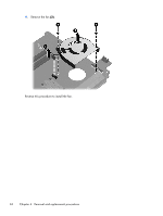
6. Remove the WWAN module (see WWAN module on page 39). 7. Disconnect the hard drive connector cable from the system board (see Hard drive on page 43). 8. Remove the keyboard (see Keyboard on page 46). 9. Disconnect the display panel cable from the system board (see Display assembly on page 49). 10. Remove the top cover (see Top cover on page 53). When replacing the system board, be sure that the following components are removed from the defective system board and installed on the replacement system board: ● SIM (see SIM on page 33) ● RTC battery (see RTC battery on page 41) ● Memory module (see Memory module on page 45) ● Power connector cable (see Power connector cable on page 60) ● Fan (see Fan on page 61) ● Heat sink (see Heat sink on page 63) Remove the system board: 1. Lift the left side of the system board (1) until it rests at an angle. 2. Remove the system board (2) by sliding it up and to the left at an angle. Reverse this procedure to install the system board. Component replacement procedures 59
-
 1
1 -
2
-
3
-
4
-
5
-
6
-
7
-
8
-
9
-
10
-
11
-
12
-
13
-
14
-
15
-
16
-
17
-
18
-
19
-
20
-
21
-
22
-
23
-
24
-
25
-
26
-
27
-
28
-
29
-
30
-
31
-
32
-
33
-
34
-
35
-
36
-
37
-
38
-
39
-
40
-
41
-
42
-
43
-
44
-
45
-
46
-
47
-
48
-
49
-
50
-
51
-
52
-
53
-
54
-
55
-
56
-
57
-
58
-
59
-
60
-
61
-
 62
62 -
 63
63 -
 64
64 -
 65
65 -
 66
66 -
 67
67 -
 68
68 -
 69
69 -
 70
70 -
 71
71 -
 72
72 -
73
-
74
-
75
-
76
-
77
-
78
-
79
-
80
-
81
-
82
-
83
-
84
-
85
-
86
-
87
-
88
-
89
-
90
-
91
-
92
-
93
-
94
-
95
 |
 |
