HP 520 HP 520 Notebook PC - Maintenance and Service Guide - Page 44
to prevent incorrect installation into the, memory module slot.
 |
View all HP 520 manuals
Add to My Manuals
Save this manual to your list of manuals |
Page 44 highlights
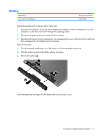
4. Spread the retaining tabs (1) on each side of the memory module slot to release the memory module. (The edge of the module opposite the slot rises away from the computer.) 5. Remove the memory module (2) by pulling the module away from the slot at an angle. NOTE: Memory modules are designed with a notch (3) to prevent incorrect installation into the memory module slot. Reverse this procedure to install a memory module. 36 Chapter 4 Removal and replacement procedures
-
 1
1 -
2
-
3
-
4
-
5
-
6
-
7
-
8
-
9
-
10
-
11
-
12
-
13
-
14
-
15
-
16
-
17
-
18
-
19
-
20
-
21
-
22
-
23
-
24
-
25
-
26
-
27
-
28
-
29
-
30
-
31
-
32
-
33
-
34
-
35
-
36
-
37
-
38
-
 39
39 -
 40
40 -
 41
41 -
 42
42 -
 43
43 -
 44
44 -
 45
45 -
 46
46 -
 47
47 -
 48
48 -
 49
49 -
50
-
51
-
52
-
53
-
54
-
55
-
56
-
57
-
58
-
59
-
60
-
61
-
62
-
63
-
64
-
65
-
66
-
67
-
68
-
69
-
70
-
71
-
72
-
73
-
74
-
75
-
76
-
77
-
78
-
79
-
80
-
81
-
82
-
83
-
84
-
85
-
86
-
87
-
88
-
89
-
90
-
91
-
92
-
93
-
94
-
95
-
96
-
97
-
98
-
99
-
100
-
101
-
102
-
103
-
104
-
105
-
106
-
107
-
108
-
109
-
110
-
111
-
112
-
113
-
114
-
115
-
116
-
117
-
118
-
119
-
120
-
121
-
122
-
123
-
124
-
125
-
126
-
127
-
128
 |
 |

4
.
Spread the retaining tabs
(1)
on each side of the memory module slot to release the memory module.
(The edge of the module opposite the slot rises away from the computer.)
5
.
Remove the memory module
(2)
by pulling the module away from the slot at an angle.
NOTE:
Memory modules are designed with a notch
(3)
to prevent incorrect installation into the
memory module slot.
Reverse this procedure to install a memory module.
36
Chapter
4
Removal and replacement procedures