HP 6125G HP 6125G & 6125G/XG Blade Switches Layer 2 - LAN Switching Co - Page 118
Configuration procedure, Verifying the configurations, Network diagram
 |
View all HP 6125G manuals
Add to My Manuals
Save this manual to your list of manuals |
Page 118 highlights
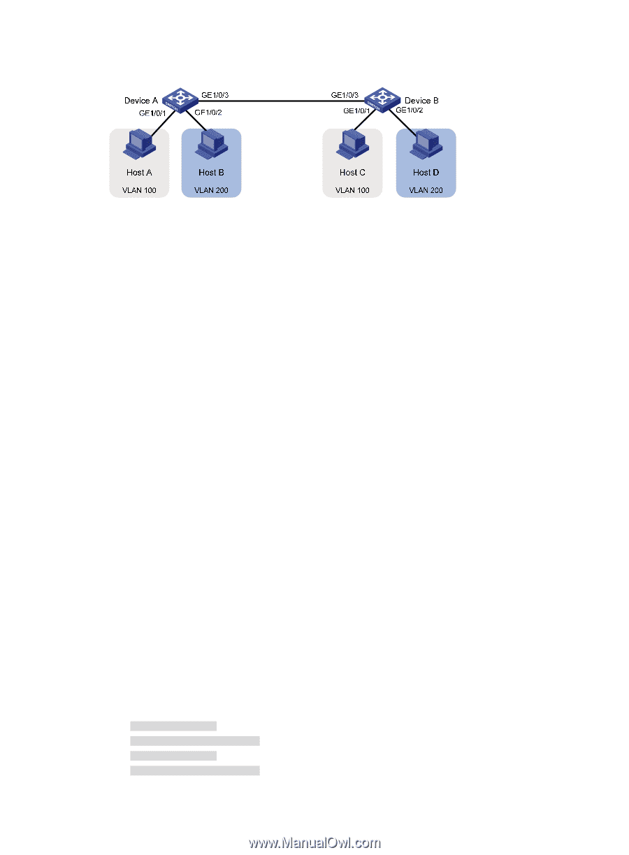
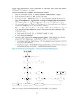
Figure 33 Network diagram Configuration procedure 1. Configure Device A: # Create VLAN 100, and assign port GigabitEthernet 1/0/1 to VLAN 100. system-view [DeviceA] vlan 100 [DeviceA-vlan100] port gigabitethernet 1/0/1 [DeviceA-vlan100] quit # Create VLAN 200, and assign port GigabitEthernet 1/0/2 to VLAN 200. [DeviceA] vlan 200 [DeviceA-vlan200] port gigabitethernet 1/0/2 [DeviceA-vlan200] quit # Configure port GigabitEthernet 1/0/3 as a trunk port, and assign it to VLANs 100 and 200, to enable GigabitEthernet 1/0/3 to forward traffic of VLANs 100 and 200 to Device B. [DeviceA] interface gigabitethernet 1/0/3 [DeviceA-GigabitEthernet1/0/3] port link-type trunk [DeviceA-GigabitEthernet1/0/3] port trunk permit vlan 100 200 Please wait... Done. 2. Configure Device B as you configure Device A. 3. Configure Host A and Host C to be on the same IP subnet, 192.168.100.0/24, for example. Configure Host B and Host D to be on the same IP subnet, 192.168.200.0/24, for example. Verifying the configurations 1. Host A and Host C and ping each other successfully, but they both fail to ping Host B. Host B and Host D and ping each other successfully, but they both fail to ping Host A. 2. Determine whether the configuration is successful by displaying relevant VLAN information. # Display information about VLANs 100 and 200 on Device A. [DeviceA-GigabitEthernet1/0/3] display vlan 100 VLAN ID: 100 VLAN Type: static Route Interface: not configured Description: VLAN 0100 Name: VLAN 0100 Tagged Ports: GigabitEthernet1/0/3 Untagged Ports: GigabitEthernet1/0/1 109
-
 1
1 -
2
-
3
-
4
-
5
-
6
-
7
-
8
-
9
-
10
-
11
-
12
-
13
-
14
-
15
-
16
-
17
-
18
-
19
-
20
-
21
-
22
-
23
-
24
-
25
-
26
-
27
-
28
-
29
-
30
-
31
-
32
-
33
-
34
-
35
-
36
-
37
-
38
-
39
-
40
-
41
-
42
-
43
-
44
-
45
-
46
-
47
-
48
-
49
-
50
-
51
-
52
-
53
-
54
-
55
-
56
-
57
-
58
-
59
-
60
-
61
-
62
-
63
-
64
-
65
-
66
-
67
-
68
-
69
-
70
-
71
-
72
-
73
-
74
-
75
-
76
-
77
-
78
-
79
-
80
-
81
-
82
-
83
-
84
-
85
-
86
-
87
-
88
-
89
-
90
-
91
-
92
-
93
-
94
-
95
-
96
-
97
-
98
-
99
-
100
-
101
-
102
-
103
-
104
-
105
-
106
-
107
-
108
-
109
-
110
-
111
-
112
-
 113
113 -
 114
114 -
 115
115 -
 116
116 -
 117
117 -
 118
118 -
 119
119 -
 120
120 -
 121
121 -
 122
122 -
 123
123 -
124
-
125
-
126
-
127
-
128
-
129
-
130
-
131
-
132
-
133
-
134
-
135
-
136
-
137
-
138
-
139
-
140
-
141
-
142
-
143
-
144
-
145
-
146
-
147
-
148
-
149
-
150
-
151
-
152
-
153
-
154
-
155
-
156
-
157
-
158
-
159
-
160
-
161
-
162
-
163
-
164
-
165
-
166
-
167
-
168
-
169
-
170
-
171
-
172
-
173
-
174
-
175
-
176
-
177
-
178
-
179
-
180
-
181
-
182
-
183
-
184
-
185
-
186
-
187
-
188
-
189
-
190
-
191
-
192
-
193
-
194
-
195
-
196
-
197
-
198
-
199
-
200
-
201
-
202
-
203
-
204
-
205
-
206
-
207
-
208
-
209
-
210
-
211
-
212
-
213
-
214
-
215
-
216
-
217
-
218
-
219
-
220
-
221
-
222
-
223
-
224
-
225
-
226
-
227
-
228
-
229
-
230
-
231
 |
 |