HP 6125G HP 6125G & 6125G/XG Blade Switches Layer 2 - LAN Switching Co - Page 54
Layer 2 dynamic aggregation configuration example, Network requirements, Configuration procedure
 |
View all HP 6125G manuals
Add to My Manuals
Save this manual to your list of manuals |
Page 54 highlights
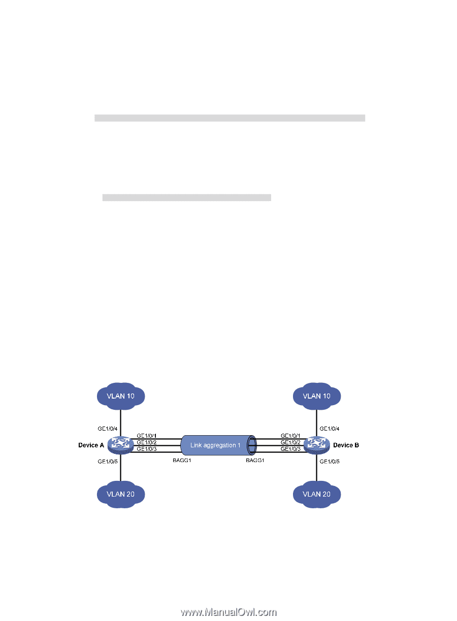
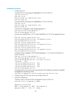
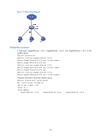
Loadsharing Type: Shar -- Loadsharing, NonS -- Non-Loadsharing Actor System ID: 0x8000, 000f-e2ff-0001 AGG AGG Partner ID Select Unselect Share Interface Mode Ports Ports Type BAGG1 S none 3 0 Shar The output shows that link aggregation group 1 is a load-shared Layer 2 static aggregation group and it contains three Selected ports. # Display the global link-aggregation load-sharing criteria on Device A. [DeviceA] display link-aggregation load-sharing mode Link-Aggregation Load-Sharing Mode: destination-mac address, source-mac address The output shows that all link aggregation groups created on the device perform load sharing based on source and destination MAC addresses. Layer 2 dynamic aggregation configuration example Network requirements As shown in Figure 10: • Device A and Device B are connected through their respective Layer 2 Ethernet interfaces GigabitEthernet 1/0/1 through GigabitEthernet 1/0/3. • Configure a Layer 2 dynamic aggregation group on both Device A and Device B, enable VLAN 10 at one end of the aggregate link to communicate with VLAN 10 at the other end, and VLAN 20 at one end to communicate with VLAN 20 at the other end. • Enable traffic to be load-shared across aggregation group member ports based on source and destination MAC addresses. Figure 10 Network diagram Configuration procedure 1. Configure Device A: # Create VLAN 10, and assign the port GigabitEthernet 1/0/4 to VLAN 10. system-view 45
-
 1
1 -
2
-
3
-
4
-
5
-
6
-
7
-
8
-
9
-
10
-
11
-
12
-
13
-
14
-
15
-
16
-
17
-
18
-
19
-
20
-
21
-
22
-
23
-
24
-
25
-
26
-
27
-
28
-
29
-
30
-
31
-
32
-
33
-
34
-
35
-
36
-
37
-
38
-
39
-
40
-
41
-
42
-
43
-
44
-
45
-
46
-
47
-
48
-
 49
49 -
 50
50 -
 51
51 -
 52
52 -
 53
53 -
 54
54 -
 55
55 -
 56
56 -
 57
57 -
 58
58 -
 59
59 -
60
-
61
-
62
-
63
-
64
-
65
-
66
-
67
-
68
-
69
-
70
-
71
-
72
-
73
-
74
-
75
-
76
-
77
-
78
-
79
-
80
-
81
-
82
-
83
-
84
-
85
-
86
-
87
-
88
-
89
-
90
-
91
-
92
-
93
-
94
-
95
-
96
-
97
-
98
-
99
-
100
-
101
-
102
-
103
-
104
-
105
-
106
-
107
-
108
-
109
-
110
-
111
-
112
-
113
-
114
-
115
-
116
-
117
-
118
-
119
-
120
-
121
-
122
-
123
-
124
-
125
-
126
-
127
-
128
-
129
-
130
-
131
-
132
-
133
-
134
-
135
-
136
-
137
-
138
-
139
-
140
-
141
-
142
-
143
-
144
-
145
-
146
-
147
-
148
-
149
-
150
-
151
-
152
-
153
-
154
-
155
-
156
-
157
-
158
-
159
-
160
-
161
-
162
-
163
-
164
-
165
-
166
-
167
-
168
-
169
-
170
-
171
-
172
-
173
-
174
-
175
-
176
-
177
-
178
-
179
-
180
-
181
-
182
-
183
-
184
-
185
-
186
-
187
-
188
-
189
-
190
-
191
-
192
-
193
-
194
-
195
-
196
-
197
-
198
-
199
-
200
-
201
-
202
-
203
-
204
-
205
-
206
-
207
-
208
-
209
-
210
-
211
-
212
-
213
-
214
-
215
-
216
-
217
-
218
-
219
-
220
-
221
-
222
-
223
-
224
-
225
-
226
-
227
-
228
-
229
-
230
-
231
 |
 |