HP 6125XLG HP 6125XLG Blade Switch FCoE NPV Mode Configuration Guidelines - Page 6
Configuration Example
 |
View all HP 6125XLG manuals
Add to My Manuals
Save this manual to your list of manuals |
Page 6 highlights
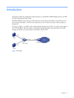
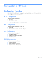
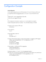
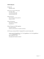
Configuration Example # FCoE Configuration # In this simple example, there are two FCoE downlinks (1/0/1 and 1/0/2) to two CNA's and # a single Ethernet LACP link-aggregated uplink (1/1/5 and 1/1/6) to the FCoE FCF switch # # Default VLAN 1 carries untagged Ethernet data traffic # VLAN 200 carries tagged FCoE traffic # # This configuration can be done in system-view, or it can be added to the config file. # system-working-mode must be set to advance - this is the default setting on 6125XLG # Configure switch to operate in NPV mode fcoe-mode npv # Create VSAN 10 vsan 10 # Create VLAN 200 in VSAN 10 vlan 200 fcoe enable vsan 10 # Configure FCoE downlink interfaces as hybrid, allowing VLANs 1 (untagged) and 200 (tagged) interface range Ten-GigabitEthernet 1/0/1 Ten-GigabitEthernet 1/0/2 port link-type hybrid port hybrid vlan 1 untagged port hybrid vlan 200 tagged # Create interface 1 with Ethernet LACP link aggregation interface bridge-aggregation 1 link-aggregation mode dynamic # Add uplink interfaces 1/1/5 and 1/1/6 to link-aggregated interface 1 # The FCF switch connected to the aggregated uplink must have LACP enabled on the attached ports interface range Ten-GigabitEthernet 1/1/5 Ten-GigabitEthernet 1/1/6 port link-aggregation group 1 Contents 6
-
 1
1 -
 2
2 -
 3
3 -
 4
4 -
 5
5 -
 6
6 -
 7
7 -
 8
8 -
 9
9
 |
 |
