HP 6715b HP Docking Station and HP Advanced Docking Station - Maintenance and
HP 6715b - Compaq Business Notebook Manual
 |
UPC - 883585514274
View all HP 6715b manuals
Add to My Manuals
Save this manual to your list of manuals |
HP 6715b manual content summary:
- HP 6715b | HP Docking Station and HP Advanced Docking Station - Maintenance and - Page 1
This guide is a troubleshooting reference used for maintaining and servicing the HP Docking Station and the HP Advanced Docking Station. It provides comprehensive information on identifying docking station features, components, and spare parts; troubleshooting problems; and performing disassembly - HP 6715b | HP Docking Station and HP Advanced Docking Station - Maintenance and - Page 2
construed as constituting an additional warranty. HP shall not be liable for technical or editorial errors or omissions contained herein. Maintenance and Service Guide HP Docking Station HP Advanced Docking Station Third Edition: May 2007 First Edition: January 2005 Document Part Number: 381882-003 - HP 6715b | HP Docking Station and HP Advanced Docking Station - Maintenance and - Page 3
Troubleshooting Checklist 2-2 2.2 Problems and Solutions 2-2 3 Illustrated Parts Catalog 3.1 Serial Number Location 3-1 3.2 Major Components 3-2 3.3 Miscellaneous Spares Kit 3-4 3.4 Sequential Part Number Listing 3-6 4 Removal and Replacement Preliminaries 4.1 Tools Required 4-1 4.2 Service - HP 6715b | HP Docking Station and HP Advanced Docking Station - Maintenance and - Page 4
Contents 5 Removal and Replacement Procedures 5.1 Serial Number 5-1 5.2 Preparing the Docking Station for Disassembly . . . . 5-2 5.3 Installing the Cable Lock 5-4 6 Specifications A Screw Listing B Connector Pin Assignments C Power Cord Set Requirements Index iv Maintenance and Service Guide - HP 6715b | HP Docking Station and HP Advanced Docking Station - Maintenance and - Page 5
desktop convenience with full port replication capability in a space-saving design. The easy docking system provides port replication and cable management in one product. The advanced docking station also provides a MultiBay II slot and an ExpressCard slot. Maintenance and Service Guide 1-1 - HP 6715b | HP Docking Station and HP Advanced Docking Station - Maintenance and - Page 6
Product Description HP Advanced Docking Station and HP Smart Adapter HP Docking Station and HP Smart Adapter 1-2 Maintenance and Service Guide - HP 6715b | HP Docking Station and HP Advanced Docking Station - Maintenance and - Page 7
PCs ■ HP Compaq nx7400 Notebook PC ■ HP Compaq nc8200, nw8200, and nx8200 Notebook PCs ■ HP Compaq nw8440, nc8430, and nx8420 Notebook PCs ■ HP Compaq 8510w and 8510p Notebook PCs ■ HP Compaq 8710w and 8710p Notebook PCs ■ HP Compaq nw9440 and nx9420 Notebook PCs Maintenance and Service Guide - HP 6715b | HP Docking Station and HP Advanced Docking Station - Maintenance and - Page 8
AC adapter (charges docked PC) ■ Lights (power, docking) ■ Integrated MultiBay II (advanced docking station only) ■ MultiBay II activity light (advanced docking station only) ■ ExpressCard slot (advanced docking station only) ■ Dual-link DVI support for following computer models: ❏ HP Compaq - HP 6715b | HP Docking Station and HP Advanced Docking Station - Maintenance and - Page 9
video (DVI) port ❏ Composite video jack ❏ RJ-45/Ethernet (network) jack ❏ RJ-11 (modem) jack ❏ Universal Serial Bus (USB) 2.0 ports ◆ Docking station-3 USB 2.0 ports ◆ Advanced docking station-5 USB 2.0 ports ❏ Powered USB port ❏ S-Video-out jack ❏ Power connector Maintenance and Service Guide 1-5 - HP 6715b | HP Docking Station and HP Advanced Docking Station - Maintenance and - Page 10
Product Description 1.2 External Components The external components on the top of the docking station are shown in the following illustration and described in Table 1-1. Top Components, Docking Station 1-6 Maintenance and Service Guide - HP 6715b | HP Docking Station and HP Advanced Docking Station - Maintenance and - Page 11
the eject button. Connects the computer to the docking station. Helps you correctly align the computer when connecting it to the docking station. Ejects the computer from the docking station. The docking light is turned on when the computer is properly aligned. Maintenance and Service Guide 1-7 - HP 6715b | HP Docking Station and HP Advanced Docking Station - Maintenance and - Page 12
Product Description The external components on the top of the advanced docking station are shown in the following illustration and described in Table 1-2. Top Components, Advanced Docking Station 1-8 Maintenance and Service Guide - HP 6715b | HP Docking Station and HP Advanced Docking Station - Maintenance and - Page 13
the eject button. Connects the computer to the docking station. Helps you correctly align the computer when connecting it to the docking station. Ejects the computer from the docking station. The docking light is turned on when the computer is properly aligned. Maintenance and Service Guide 1-9 - HP 6715b | HP Docking Station and HP Advanced Docking Station - Maintenance and - Page 14
following illustration and described in Table 1-3. Left-Side Components, Docking Station Table 1-3 Left-Side Components, Docking Station Item 1 Component Power button and power light 2 USB port 3 Powered USB port Description Turns on power to the computer. The light indicates the state of - HP 6715b | HP Docking Station and HP Advanced Docking Station - Maintenance and - Page 15
as hard drives and optical drives. Allow you to connect USB devices. Allows you to connect to select USB devices. Allows you to connect ExpressCard devices to the docking station. Turns on power to the computer. The light is turned on when the computer is turned on. Maintenance and Service Guide - HP 6715b | HP Docking Station and HP Advanced Docking Station - Maintenance and - Page 16
button and dock light Integrated cable lock slot Description Ejects the computer from the docking station. The dock light is turned on when the computer is properly aligned. Supports the cable lock, which secures the docking station and a connected computer. 1-12 Maintenance and Service Guide - HP 6715b | HP Docking Station and HP Advanced Docking Station - Maintenance and - Page 17
and docking light Ejects the computer from the docking station. The docking light is turned on when the computer is properly aligned. Integrated cable lock slot Supports the cable lock, which secures the docking station, connected computer, and MultiBay II drive. Maintenance and Service Guide - HP 6715b | HP Docking Station and HP Advanced Docking Station - Maintenance and - Page 18
cable lock. Connects an optional HP Monitor Stand to the docking station. Connects an audio output device such as headphones or speakers. Connects a PS/2 mouse. Connects a parallel device such as a printer. Connects a DVI device such as a flat panel monitor. 1-14 Maintenance and Service Guide - HP 6715b | HP Docking Station and HP Advanced Docking Station - Maintenance and - Page 19
the docking station is connected to AC power. Connects a telephone cable. Connects a network cable. Connect USB devices. Connects the docking station to the HP Smart Adapter AC adapter. Connects a VGA monitor. Connects a serial device such as a mouse. Connects a PS/2 keyboard. Connects home audio - HP 6715b | HP Docking Station and HP Advanced Docking Station - Maintenance and - Page 20
Docking Station Table 1-8 Rear Components, Advanced Docking Station Item 1 2 3 4 Component Security cable slot Audio- audio output device such as headphones or speakers. Connects a PS/2 mouse. Connects an optional HP Monitor Stand to the docking station. 1-16 Maintenance and Service Guide - HP 6715b | HP Docking Station and HP Advanced Docking Station - Maintenance and - Page 21
. Connects a network cable. Connect USB devices. Connects the docking station to the HP Smart Adapter AC adapter. Connects a VGA monitor. Connects a serial device such as a mouse. Connects a PS/2 keyboard. Connects home audio equipment such as CD and MP3 players. Maintenance and Service Guide 1-17 - HP 6715b | HP Docking Station and HP Advanced Docking Station - Maintenance and - Page 22
3, "Illustrated Parts Catalog," to identify replacement parts, and Chapter 5, "Removal and Replacement Procedures," for disassembly steps. The docking stations provide the following device connections: ■ Monitor stand port, for use with the HP Monitor Stand ■ Digital video (DVI) jack ■ Audio-out - HP 6715b | HP Docking Station and HP Advanced Docking Station - Maintenance and - Page 23
contains troubleshooting information for the HP Docking Station and HP Advanced Docking Station. Carefully match the symptoms of the malfunction against the problem description in the troubleshooting tables to avoid a misdiagnosis. Refer to Chapter 5 for all removal and replacement procedures - HP 6715b | HP Docking Station and HP Advanced Docking Station - Maintenance and - Page 24
. If accessories are attached, they should now work properly. The computer is turned on and properly docked, but the power light and dock light are not on. Power cord is not plugged into either the docking station or the AC outlet. Properly plug in power cord. 2-2 Maintenance and Service Guide - HP 6715b | HP Docking Station and HP Advanced Docking Station - Maintenance and - Page 25
Troubleshooting Docking Problems and Solutions (Continued) Problem Possible Cause Solution Some of the ports or connectors do not work, even though the docking light is turned on. The computer may be properly aligned, but is not fully seated or docked in the docking station. Press the eject - HP 6715b | HP Docking Station and HP Advanced Docking Station - Maintenance and - Page 26
Troubleshooting Undocking Problems and Solutions Problem The computer will not disconnect from the docking station. Possible Cause Solution The connectors may be jammed. Press the eject button . Unlock the cable lock and then disconnect the computer. 2-4 Maintenance and Service Guide - HP 6715b | HP Docking Station and HP Advanced Docking Station - Maintenance and - Page 27
and then restart the computer. Cabling is incorrect. Ensure that the device cable is in the correct connector on the docking station. You may need to install device drivers on the computer. Install drivers according to the device manufacturer's instructions. Maintenance and Service Guide 2-5 - HP 6715b | HP Docking Station and HP Advanced Docking Station - Maintenance and - Page 28
the media tray. There is no power to the advanced docking station. ■ Turn on power to the system, and then eject the disc. ■ Manually eject the disc. MultiBay II Problems and Solutions Problem The MultiBay II drive is not recognized. Possible Cause The drive is not properly inserted in the - HP 6715b | HP Docking Station and HP Advanced Docking Station - Maintenance and - Page 29
and a reference for spare part numbers and option part numbers. 3.1 Serial Number Location When ordering parts or requesting information, provide the docking station serial number and model number located on the bottom of the base plate. Serial Number Location Maintenance and Service Guide 3-1 - HP 6715b | HP Docking Station and HP Advanced Docking Station - Maintenance and - Page 30
Illustrated Parts Catalog 3.2 Major Components Major Components, HP Docking Station and HP Advanced Docking Station 3-2 Maintenance and Service Guide - HP 6715b | HP Docking Station and HP Advanced Docking Station - Maintenance and - Page 31
Illustrated Parts Catalog Table 3-1 HP Docking Station/HP Advanced Docking Station Major Components Item 1 2 3 4 Description HP Docking Station (whole unit replacement) HP Advanced Docking Station (whole unit replacement) Power cord For use in Australia For use in Brazil For use in Denmark For - HP 6715b | HP Docking Station and HP Advanced Docking Station - Maintenance and - Page 32
Illustrated Parts Catalog 3.3 Miscellaneous Spares Kit Miscellaneous Spares Kit 3-4 Maintenance and Service Guide - HP 6715b | HP Docking Station and HP Advanced Docking Station - Maintenance and - Page 33
Part Number Miscellaneous Plastics Kit, includes: 380089-001 MultiBay II dummy card ExpressCard slot dummy card Large rubber feet, 5 each Small rubber feet, 2 each Rubber bumper (protects unit and computer when docking) Cable lock bezel blank Cable lock bezel Maintenance and Service Guide - HP 6715b | HP Docking Station and HP Advanced Docking Station - Maintenance and - Page 34
cord for use in Denmark Power cord for use in Brazil Power cord for use in Japan Power cord for use in Korea Power cord for use in Switzerland Miscellaneous Plastics Kit AC adapter, 120-W, PFC AC adapter, 135-W, PFC HP Docking Station HP Advanced Docking Station 3-6 Maintenance and Service Guide - HP 6715b | HP Docking Station and HP Advanced Docking Station - Maintenance and - Page 35
include some of the considerations that you should keep in mind during disassembly and assembly procedures. ✎ As you remove each subassembly from the docking base, place the subassembly (and all accompanying screws) away from the work area to prevent damage. Maintenance and Service Guide 4-1 - HP 6715b | HP Docking Station and HP Advanced Docking Station - Maintenance and - Page 36
and Replacement Preliminaries Plastic Parts Using excessive force during disassembly and reassembly can damage plastic parts. Use care when handling the plastic parts. Apply pressure only at the points designated in the maintenance instructions. Cables and Connectors Ä CAUTION: When servicing the - HP 6715b | HP Docking Station and HP Advanced Docking Station - Maintenance and - Page 37
Replacement Preliminaries 4.4 Packaging and Transporting Precautions Use the following grounding precautions when packaging and transporting equipment: ■ To avoid hand contact, transport products in static-safe containers, such as tubes, bags, or boxes. ■ Protect all electrostatic-sensitive parts - HP 6715b | HP Docking Station and HP Advanced Docking Station - Maintenance and - Page 38
Replacement Preliminaries 4.5 Workstation Precautions Use the following grounding precautions at workstations: ■ Cover Styrofoam. ■ Handle electrostatic-sensitive components, parts, and assemblies by the case or , or circuitry. ■ Turn off power and input signals before inserting or Service Guide - HP 6715b | HP Docking Station and HP Advanced Docking Station - Maintenance and - Page 39
Removal and Replacement Preliminaries ■ When standing, use foot straps and a grounded floor mat. cords of one megohm resistance. ■ Static-dissipative tables or floor mats with hard ties to the ground. ■ Field service kits. ■ Static awareness labels. ■ Material-handling packages. ■ Nonconductive - HP 6715b | HP Docking Station and HP Advanced Docking Station - Maintenance and - Page 40
Removal and Replacement Preliminaries Table 4-1 shows how humidity affects the electrostatic voltage levels generated by different activities. Table 4-1 Typical Bags 1,500 V Carbon-loaded plastic Floor mats 7,500 V Metallized laminate Floor mats 5,000 V 4-6 Maintenance and Service Guide - HP 6715b | HP Docking Station and HP Advanced Docking Station - Maintenance and - Page 41
information on screw sizes, locations, and usage. 5.1 Serial Number Report the docking station serial number to HP when requesting information or ordering spare parts. The serial number is located on the bottom of the docking station. Serial Number Location Maintenance and Service Guide 5-1 - HP 6715b | HP Docking Station and HP Advanced Docking Station - Maintenance and - Page 42
Removal and Replacement Procedures 5.2 Preparing the Docking Station for Disassembly Perform the following steps before disassembling the docking station: 1. If a computer is connected to the docking station, close the computer. If you close the computer with the power turned on, the computer may - HP 6715b | HP Docking Station and HP Advanced Docking Station - Maintenance and - Page 43
the eject button 1. The computer disconnects from the docking station. 3. Lift up the computer 2 and set it aside. Undocking the Computer 4. Disconnect all external devices connected to the docking station. 5. Disconnect the power cord from the docking station. Maintenance and Service Guide 5-3 - HP 6715b | HP Docking Station and HP Advanced Docking Station - Maintenance and - Page 44
, or the advanced docking station with a docked computer and MultiBay II drive installed. Install the cable lock into the integrated cable lock slot on the right side of the docking station, as shown in the following illustrations. Identifying the Cable Lock Slot 5-4 Maintenance and Service Guide - HP 6715b | HP Docking Station and HP Advanced Docking Station - Maintenance and - Page 45
Turn the docking station upside down, and then remove the three PM2.5x5 screws from the cable lock bezel 1. 3. Remove the bezel from the docking station 2, and then remove the bezel blank from the cable lock bezel 3. Removing the Cable Lock Bezel and Bezel Blank Maintenance and Service Guide 5-5 - HP 6715b | HP Docking Station and HP Advanced Docking Station - Maintenance and - Page 46
the t-bar on the back of the lock in the vertical position, insert the lock into the center groove in the cable lock slot in the docking station 1. 5. Insert the cable into the recessed cable channel in the base of the docking station 2. Inserting the Cable Lock 5-6 Maintenance and Service Guide - HP 6715b | HP Docking Station and HP Advanced Docking Station - Maintenance and - Page 47
Removal and Replacement Procedures 6. Turn the key counterclockwise to lock 1. 7. Remove the key from the lock 2. 8. Reinsert the cable lock bezel onto the docking station 3. 9. Replace the screws to secure the bezel 4. Securing the Cable Lock Maintenance and Service Guide 5-7 - HP 6715b | HP Docking Station and HP Advanced Docking Station - Maintenance and - Page 48
Removal and Replacement Procedures The following illustration shows a docking station with the cable lock installed. Docking Station with Cable Lock Inserted 5-8 Maintenance and Service Guide - HP 6715b | HP Docking Station and HP Advanced Docking Station - Maintenance and - Page 49
physical and performance specifications. Table 6-1 HP Docking Station Specifications Dimensions Height Width Length 28.0 38.7°C (101.6°F) maximum wet bulb temperature Power Supply Rated Voltage Rated Current Line Frequency 100 to 240V 2.5A rms 50 - 60 Hz Maintenance and Service Guide 6-1 - HP 6715b | HP Docking Station and HP Advanced Docking Station - Maintenance and - Page 50
Specifications Table 6-1 HP Docking Station Specifications (Continued) Altitude Operating Non-operating 0 m to 3,048 m 0 m to 9,144 m 0 ft to 10,000 ft 0 ft to 30,000 ft to 500 Hz, 0.25 oct/min sweep rate 1 G, zero-to-peak, 10 to 500 Hz, 0.5 oct/min sweep rate 6-2 Maintenance and Service Guide - HP 6715b | HP Docking Station and HP Advanced Docking Station - Maintenance and - Page 51
Specifications Table 6-2 HP Advanced Docking Station Specifications Dimensions Height Width Length 28.0 cm 90% 5% to 90%, 38.7°C (101.6°F) maximum wet bulb temperature Power Supply Rated Voltage Rated Current Line Frequency 100 to 240V 2.5A rms 50 - 60 Hz Maintenance and Service Guide 6-3 - HP 6715b | HP Docking Station and HP Advanced Docking Station - Maintenance and - Page 52
Specifications Table 6-2 HP Advanced Docking Station Specifications (Continued) Altitude Operating Non-operating 0 m to 3,048 m 0 m to 9,144 m 0 ft to 10,000 ft 0 ft to 30, 500 Hz, 0.25 oct/min sweep rate 1 G, zero-to-peak, 10 to 500 Hz, 0.5 oct/min sweep rate 6-4 Maintenance and Service Guide - HP 6715b | HP Docking Station and HP Advanced Docking Station - Maintenance and - Page 53
A Screw Listing This appendix provides specification and reference information for the screws used in the HP Docking Station and the HP Advanced Docking Station. Maintenance and Service Guide A-1 - HP 6715b | HP Docking Station and HP Advanced Docking Station - Maintenance and - Page 54
Listing Table A-1 Phillips M2.5×5.0 Screw Head mm Color Qty. Length Thread Width Black 3 5.0 mm 2.5 mm 4.0 mm Where used: Three screws that secure the cable lock cover to the base enclosure (documented in Section 5.3) Phillips M2.5×5.0 Screw Locations A-2 Maintenance and Service Guide - HP 6715b | HP Docking Station and HP Advanced Docking Station - Maintenance and - Page 55
B Connector Pin Assignments Table B-1 Audio-In (Microphone) Jack Pin Signal 1 Audio signal in 2 Audio signal in Pin Signal 3 Ground Maintenance and Service Guide B-1 - HP 6715b | HP Docking Station and HP Advanced Docking Station - Maintenance and - Page 56
Connector Pin Assignments Table B-2 Audio-Out (Headphone) Jack Pin Signal 1 Audio out, left channel 2 Audio out, right channel Pin Signal 3 Ground B-2 Maintenance and Service Guide - HP 6715b | HP Docking Station and HP Advanced Docking Station - Maintenance and - Page 57
analog Pin Signal 9 +5 VDC 10 Ground 11 Monitor detect 12 DDC 2B data 13 Horizontal sync 14 Vertical sync 15 DDC 2B clock Maintenance and Service Guide B-3 - HP 6715b | HP Docking Station and HP Advanced Docking Station - Maintenance and - Page 58
Connector Pin Assignments Table B-4 Keyboard/Mouse Connector Pin Signal 1 Keyboard/mouse DATA 2 Keyboard/mouse DATA 3 Ground Pin Signal 4 +5 VDC 5 Keyboard/mouse CLK 6 Keyboard/mouse CLK B-4 Maintenance and Service Guide - HP 6715b | HP Docking Station and HP Advanced Docking Station - Maintenance and - Page 59
Error 16 Initialize printer 17 Select in 18 Ground 19 Ground 20 Ground 21 Ground 22 Ground 23 Ground 24 Ground 25 Ground Maintenance and Service Guide B-5 - HP 6715b | HP Docking Station and HP Advanced Docking Station - Maintenance and - Page 60
3 Ring Pin Signal 4 Unused 5 Unused 6 Unused Table B-7 RJ-45 (Network) Jack Pin Signal 1 Transmit + 2 Transmit - 3 Receive + 4 Unused B-6 Pin Signal 5 Unused 6 Receive - 7 Unused 8 Unused Maintenance and Service Guide - HP 6715b | HP Docking Station and HP Advanced Docking Station - Maintenance and - Page 61
Connector Pin Assignments Table B-8 Serial Port Pin Signal 1 Carrier detect 2 Receive data 3 Transmit data 4 Data terminal ready 5 Ground Pin Signal 6 Data set ready 7 Ready to send 8 Clear to send 9 Ring indicator Maintenance and Service Guide B-7 - HP 6715b | HP Docking Station and HP Advanced Docking Station - Maintenance and - Page 62
-Ground Pin Signal 5 TV-CD 6 TV-Ground 7 TV-YD Table B-10 Universal Serial Bus Port Pin Signal 1 +5 VDC 2 Data - B-8 Pin Signal 3 Data + 4 Ground Maintenance and Service Guide - HP 6715b | HP Docking Station and HP Advanced Docking Station - Maintenance and - Page 63
included with the docking station meets the requirements for use in the country or region where the equipment is purchased. Power cord sets for use in other countries or regions must meet the requirements of the country or region where the docking station is used. Maintenance and Service Guide C-1 - HP 6715b | HP Docking Station and HP Advanced Docking Station - Maintenance and - Page 64
of 125 or 250 V AC, as required by each country's or region's power system. ■ The appliance coupler must meet the mechanical configuration of an EN 60 320/IEC 320 Standard Sheet C13 connector for mating with the appliance inlet on the back of the docking station. C-2 Maintenance and Service Guide - HP 6715b | HP Docking Station and HP Advanced Docking Station - Maintenance and - Page 65
1. The flexible cord must be Type HO5VV-F, 3-conductor, 1.0 mm² conductor size. Power cord set fittings (appliance coupler and wall plug) must bear the certification mark of the agency with a Japanese Industrial Standard C8303 (7 A, 125 V) configuration. Maintenance and Service Guide C-3 - HP 6715b | HP Docking Station and HP Advanced Docking Station - Maintenance and - Page 66
Power HO5VV-F, 3-conductor, 1.0 mm² conductor size. Power cord set fittings (appliance coupler and wall plug) 3-conductor, 0.75 mm² conductor size. Power cord set fittings (appliance coupler and wall VCTF, 3-conductor, 0.75 mm² conductor size. Power cord set fittings (appliance coupler and wall plug) - HP 6715b | HP Docking Station and HP Advanced Docking Station - Maintenance and - Page 67
6-3 See also docking station audio-in jack location 1-15, 1-17 pin assignments B-1 audio-out jack location 1-14, 1-16 pin assignments B-2 B bumper, spare part number 3-5 C cable lock bezel blank, spare part number 3-5 cable lock bezel, spare part number 3-5 cable lock slot 1-12, 1-13 cables, service - HP 6715b | HP Docking Station and HP Advanced Docking Station - Maintenance and - Page 68
1-14, 1-17 disconnection troubleshooting 2-4, 2-5 docking connector 1-7, 1-9 docking light 1-7, 1-9, 1-12 docking posts 1-7, 1-9 docking problems 2-2, 2-3 docking station spare part number 3-3, 3-6 specifications 6-1 See also advanced docking station dummy card ExpressCard 3-5 MultiBay II 3-5 DVI - HP 6715b | HP Docking Station and HP Advanced Docking Station - Maintenance and - Page 69
spare part number 3-5 rubber feet, spare part number 3-5 S screw listing A-1 security cable slot 1-14, 1-16 serial number 3-1, 5-1 serial port location 1-15, 1-17 pin assignments B-7 service considerations 4-1 spare part number advanced docking station 3-3, 3-6 Maintenance and Service Guide Index - HP 6715b | HP Docking Station and HP Advanced Docking Station - Maintenance and - Page 70
Kit 3-4 power cord 3-3 specifications advanced docking station 6-3 docking station 6-1 static-shielding materials 4-6 S-Video-out jack location 1-15, 1-17 pin assignments B-8 T tools required 4-1 top components 1-6, 1-8 transporting precautions 4-3 troubleshooting checklist 2-1 U undocking problems
-
 1
1 -
 2
2 -
 3
3 -
 4
4 -
 5
5 -
 6
6 -
 7
7 -
8
-
9
-
10
-
11
-
12
-
13
-
14
-
15
-
16
-
17
-
18
-
19
-
20
-
21
-
22
-
23
-
24
-
25
-
26
-
27
-
28
-
29
-
30
-
31
-
32
-
33
-
34
-
35
-
36
-
37
-
38
-
39
-
40
-
41
-
42
-
43
-
44
-
45
-
46
-
47
-
48
-
49
-
50
-
51
-
52
-
53
-
54
-
55
-
56
-
57
-
58
-
59
-
60
-
61
-
62
-
63
-
64
-
65
-
66
-
67
-
68
-
69
-
70
 |
 |

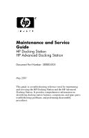
Maintenance and Service
Guide
HP Docking Station
HP Advanced Docking Station
Document Part Number: 381882-003
May 2007
This guide is a troubleshooting reference used for maintaining
and servicing the HP Docking Station and the HP Advanced
Docking Station. It provides comprehensive information on
identifying docking station features, components, and spare parts;
troubleshooting problems; and performing disassembly
procedures.