HP 6715b HP Docking Station and HP Advanced Docking Station - Maintenance and - Page 67
Index
 |
UPC - 883585514274
View all HP 6715b manuals
Add to My Manuals
Save this manual to your list of manuals |
Page 67 highlights
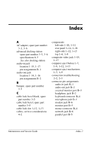
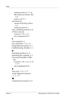
Index A AC adapter, spare part number 3-3, 3-6 advanced docking station spare part number 3-3, 3-6 specifications 6-3 See also docking station audio-in jack location 1-15, 1-17 pin assignments B-1 audio-out jack location 1-14, 1-16 pin assignments B-2 B bumper, spare part number 3-5 C cable lock bezel blank, spare part number 3-5 cable lock bezel, spare part number 3-5 cable lock slot 1-12, 1-13 cables, service considerations 4-2 components left-side 1-10, 1-11 rear panel 1-14, 1-16 right-side 1-12, 1-13 top 1-6, 1-8 composite video jack 1-15, 1-17 computer eject button 1-7, 1-9, 1-12, 1-13 computer eject mechanisms 1-7, 1-9 connection troubleshooting 2-2, 2-3 connector pin assignments audio-in jack B-1 audio-out jack B-2 external monitor port B-3 headphone jack B-2 keyboard connector B-4 microphone jack B-1 modem jack B-6 monitor port B-3 mouse connector B-4 network jack B-6 parallel port B-5 Maintenance and Service Guide Index-1
-
 1
1 -
2
-
3
-
4
-
5
-
6
-
7
-
8
-
9
-
10
-
11
-
12
-
13
-
14
-
15
-
16
-
17
-
18
-
19
-
20
-
21
-
22
-
23
-
24
-
25
-
26
-
27
-
28
-
29
-
30
-
31
-
32
-
33
-
34
-
35
-
36
-
37
-
38
-
39
-
40
-
41
-
42
-
43
-
44
-
45
-
46
-
47
-
48
-
49
-
50
-
51
-
52
-
53
-
54
-
55
-
56
-
57
-
58
-
59
-
60
-
61
-
 62
62 -
 63
63 -
 64
64 -
 65
65 -
 66
66 -
 67
67 -
 68
68 -
 69
69 -
 70
70
 |
 |