HP Blackbird 002-21A HP Blackbird Gaming System - Upgrading and Servicing
HP Blackbird 002-21A Manual
 |
View all HP Blackbird 002-21A manuals
Add to My Manuals
Save this manual to your list of manuals |
HP Blackbird 002-21A manual content summary:
- HP Blackbird 002-21A | HP Blackbird Gaming System - Upgrading and Servicing - Page 1
Upgrading and Servicing Guide - HP Blackbird 002-21A | HP Blackbird Gaming System - Upgrading and Servicing - Page 2
services. Nothing herein should be construed as constituting an additional warranty. HP shall not be liable for technical or editorial errors or omissions contained herein. HP in the United States and/or other countries/regions. HP supports lawful use of technology and does not endorse or encourage - HP Blackbird 002-21A | HP Blackbird Gaming System - Upgrading and Servicing - Page 3
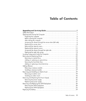
35 Removing a memory module 36 Installing a memory module 37 Removing and Installing an Add-in Card 39 Removing an add-in card 39 Installing an add-in card 42 Removing and Replacing the Power Supply 45 Removing the power supply 45 Replacing the power supply 47 Removing and Replacing the SATA - HP Blackbird 002-21A | HP Blackbird Gaming System - Upgrading and Servicing - Page 4
iv Table of Contents - HP Blackbird 002-21A | HP Blackbird Gaming System - Upgrading and Servicing - Page 5
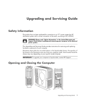
and Support Guide before installing and connecting your computer to the electrical power system. This Upgrading and Servicing Guide provides instructions for removing and replacing hardware components of your computer. Illustrations show either the air-cooled chassis or the liquid-cooled chassis - HP Blackbird 002-21A | HP Blackbird Gaming System - Upgrading and Servicing - Page 6
any memory card or optical disc (CD or DVD) from the computer. 2 Shut down the computer. 3 Turn off the computer power supply by using the rocker switch on the back of the chassis. 4 Disconnect the power static electricity by briefly touching a grounded metal object. 2 Upgrading and Servicing Guide - HP Blackbird 002-21A | HP Blackbird Gaming System - Upgrading and Servicing - Page 7
, and then turn on all peripherals, such as the monitor. 6 If you installed an add-in card, install any software drivers supplied by the card manufacturer. Accessing the chassis through the access door (left side) To upgrade or service the majority of components in the computer, you must access the - HP Blackbird 002-21A | HP Blackbird Gaming System - Upgrading and Servicing - Page 8
, lift the front edge of the door latch (A), and then swing the door open. A The door opens until it is about 85 degrees to the chassis. Do not force the door to open more than 85 degrees. WARNING: Beware of sharp edges inside the chassis. 4 Upgrading and Servicing Guide - HP Blackbird 002-21A | HP Blackbird Gaming System - Upgrading and Servicing - Page 9
3 To remove the exterior door inlay when replacing it: NOTE: Do not remove the access door from the chassis hinges during these steps. a Remove the inlay screw (B) from the inside of the door. B b Close the door. Upgrading and Servicing Guide 5 - HP Blackbird 002-21A | HP Blackbird Gaming System - Upgrading and Servicing - Page 10
pull out the square-cornered edge of the inlay (C, near the rear of the chassis) to free the three snaps along the left side of the inlay. b Continue of the chassis to free it. d Set the inlay aside. C To install the inlay, see "Replacing the access door" on page 8. 6 Upgrading and Servicing Guide - HP Blackbird 002-21A | HP Blackbird Gaming System - Upgrading and Servicing - Page 11
4 To remove the door from the chassis hinges: a Open the door fully so that it is at 85 degrees to the chassis. b Lift up the door about 2.54 cm (1 inch) until the hinges clear the hinge pins. c Set the door aside. Upgrading and Servicing Guide 7 - HP Blackbird 002-21A | HP Blackbird Gaming System - Upgrading and Servicing - Page 12
Replacing the access door Complete the following steps to place the left access door on its more than 85 degrees. a Position the door completely open at 85 degrees to the chassis. b Insert the back edge of the door into the chassis, with the hinges over the hinge pins. 8 Upgrading and Servicing Guide - HP Blackbird 002-21A | HP Blackbird Gaming System - Upgrading and Servicing - Page 13
the inlay onto the door just to the left of the slots (E), while maintaining the vertical alignment. c Slide the inlay toward the front of the chassis, inserting the three tabs (D) on the inlay into the slots (E) in the door. F E F F D G GG Upgrading and Servicing Guide 9 - HP Blackbird 002-21A | HP Blackbird Gaming System - Upgrading and Servicing - Page 14
to bottom again, to engage the last column of snap studs (J). d Open the door. e Insert the inlay screw (B) on the inside of the door. B 10 Upgrading and Servicing Guide - HP Blackbird 002-21A | HP Blackbird Gaming System - Upgrading and Servicing - Page 15
, and power supply baffle): 1 Open the access door. See "Accessing the chassis through the access door (left side)" on page 3. 2 Open the PCI door by moving the latch (K) to the left, and then swinging the door open. If necessary, lift up the door to remove it from the hinges. L K M Upgrading and - HP Blackbird 002-21A | HP Blackbird Gaming System - Upgrading and Servicing - Page 16
3 Remove the thermal divider (L) by pulling it straight out of the chassis. L 4 Remove the power supply baffle by pulling the baffle (M) straight out of the chassis. M 12 Upgrading and Servicing Guide - HP Blackbird 002-21A | HP Blackbird Gaming System - Upgrading and Servicing - Page 17
1 Replace the power supply baffle by positioning the baffle onto the guide rails (M1), and then sliding the baffle straight into the chassis. L1 M1 2 Replace the thermal divider by positioning the divider onto the guide rails (L1), and then sliding the divider straight into the chassis. 3 Replace - HP Blackbird 002-21A | HP Blackbird Gaming System - Upgrading and Servicing - Page 18
Complete the following steps to access the right side of the chassis to replace the inlay or the SATA backplane. You must remove the the inlay screw (N) from the inside of the chassis. NOTE: The inlay screw (N) is a captive screw. Do not remove it from the chassis. N 14 Upgrading and Servicing Guide - HP Blackbird 002-21A | HP Blackbird Gaming System - Upgrading and Servicing - Page 19
to the panel, slide the inlay toward the back of the chassis to free it. d Set the inlay aside. O This completes the steps to remove the inlay. Continue with step 3 to access the SATA backplane. To install the inlay, see "Replacing the right side access" on page 18. Upgrading and Servicing Guide 15 - HP Blackbird 002-21A | HP Blackbird Gaming System - Upgrading and Servicing - Page 20
3 To open the right access panel: a Remove the three screws (P) that secure the panel. P b Swing open the panel. 16 Upgrading and Servicing Guide - HP Blackbird 002-21A | HP Blackbird Gaming System - Upgrading and Servicing - Page 21
The access panel opens until it is about 85 degrees to the chassis. Do not force the panel to open more than 85 degrees. CAUTION: To avoid damage, do not open the panel more than 85 degrees. WARNING: Beware of sharp edges inside the chassis. Upgrading and Servicing Guide 17 - HP Blackbird 002-21A | HP Blackbird Gaming System - Upgrading and Servicing - Page 22
edge of the panel into the chassis with the hinges over the hinge pins. c Lower the panel onto the hinges. CAUTION: To avoid damaging the panel, check that both of the panel hinges are properly seated onto the hinge pins before closing the panel. 2 Close the panel. 18 Upgrading and Servicing Guide - HP Blackbird 002-21A | HP Blackbird Gaming System - Upgrading and Servicing - Page 23
3 Insert three screws (P) to secure the panel. P Upgrading and Servicing Guide 19 - HP Blackbird 002-21A | HP Blackbird Gaming System - Upgrading and Servicing - Page 24
. c Slide the inlay toward the front of the chassis inserting the three tabs (S) on the inlay into the slots (T) in the panel. Q T Q Q S R RR CAUTION: To avoid damaging the inlay, do not hold or pull out the inlay more than 2.54 cm (1 inch) away from the panel. 20 Upgrading and Servicing Guide - HP Blackbird 002-21A | HP Blackbird Gaming System - Upgrading and Servicing - Page 25
(V). g Move near the right edge of the inlay and press the inlay from top to bottom again to engage the last column of snap studs (W). Upgrading and Servicing Guide 21 - HP Blackbird 002-21A | HP Blackbird Gaming System - Upgrading and Servicing - Page 26
Locating Components Inside the Computer A Add-in cards: PCI and PCI-E slots B Memory C Access door (left side) with additional bays for optional hard disk drives J Power supply NOTE: The connectors and components of your chassis model may vary from the illustration. 22 Upgrading and Servicing Guide - HP Blackbird 002-21A | HP Blackbird Gaming System - Upgrading and Servicing - Page 27
replace or upgrade. See "Locating Components Inside the Computer" on page 22 for drive locations. The primary hard disk drive, as well as each of the optional hard disk drives, is a Serial ATA (advanced technology attachment) drive. The chassis operating system. Upgrading and Servicing Guide 23 - HP Blackbird 002-21A | HP Blackbird Gaming System - Upgrading and Servicing - Page 28
the chassis), which may be a drive or a filler. The following figure on the right shows the slim drive assembly, including the pins of the data connector (D) and the power connector (E). D A E B C B/C 3 Release the drives by pulling out the optical drive latch (H). H 24 Upgrading and Servicing Guide - HP Blackbird 002-21A | HP Blackbird Gaming System - Upgrading and Servicing - Page 29
4 Push the full-size drive (or filler) partway out through the front of the chassis. 5 Remove the optional slim optical disc drive by pulling the drive tab (B) toward the inside of the chassis, and then rotating it toward you and out of the chassis. B Upgrading and Servicing Guide 25 - HP Blackbird 002-21A | HP Blackbird Gaming System - Upgrading and Servicing - Page 30
motion to free the power plug; press the latch on the data plug, and then pull it from the connector. The following figure shows the location of the back of the full-size optical disc drive filler (A), which has rails that attach to an optional full-size drive. A 26 Upgrading and Servicing Guide - HP Blackbird 002-21A | HP Blackbird Gaming System - Upgrading and Servicing - Page 31
3 Release the drive by pulling out the optical drive latch (H). H 4 Remove the drive by pushing it out through the front of the chassis. Upgrading and Servicing Guide 27 - HP Blackbird 002-21A | HP Blackbird Gaming System - Upgrading and Servicing - Page 32
drive is in an adapter. Get your replacement slim drive assembly (drive in the adapter) from HP. Adding or replacing a slim optical disc drive 1 If chassis until the assembly is completely seated. The light bar (A) should extend out of the front of the chassis. 28 Upgrading and Servicing Guide - HP Blackbird 002-21A | HP Blackbird Gaming System - Upgrading and Servicing - Page 33
of the slim optical disc drive assembly B Tab on the primary or the optional slim optical disc drive C Alignment knobs D Power connector (pins) E Data connector (pins) F Slots for slim optical disc drives: (F1) is primary drive slot, (F2) is optional drive slot C B Upgrading and Servicing Guide 29 - HP Blackbird 002-21A | HP Blackbird Gaming System - Upgrading and Servicing - Page 34
the drives by pushing in the optical drive latch (H). H 5 Connect the data cable plug and the power cable plug to the connectors on the back of the slim optical disk drives. 6 Close the access door and the computer. See "Opening and Closing the Computer" on page 1. 30 Upgrading and Servicing Guide - HP Blackbird 002-21A | HP Blackbird Gaming System - Upgrading and Servicing - Page 35
the right side of the unit. e Place the rail, with the notch (D) facing down, on the right side of the replacement drive. Align the holes in the rail labeled B with the top row of holes on the drive, and then insert the screws through the B holes in the rail. Upgrading and Servicing Guide 31 - HP Blackbird 002-21A | HP Blackbird Gaming System - Upgrading and Servicing - Page 36
the right. Specifically, the disc tray (E) faces toward the right. Slowly insert the drive into the chassis through the front. If the drive starts to bind or becomes stuck, stop inserting it. Remove the 3 Secure the drive by pushing in the optical drive latch (H). H 32 Upgrading and Servicing Guide - HP Blackbird 002-21A | HP Blackbird Gaming System - Upgrading and Servicing - Page 37
4 Connect the data cable plug and the power cable plug into the connectors of the replacement full-size optical disc drive. If you are adding a drive, route the cables and connect them at the motherboard and the power supply. 5 Close the access door and the computer. See "Opening and Closing the - HP Blackbird 002-21A | HP Blackbird Gaming System - Upgrading and Servicing - Page 38
Adding or replacing a hard disk drive 1 If necessary, remove the existing drive. See "Removing drive. C D E D E WARNING: The lowest of the five hard disk drive drawer slots contains the operating system. If you install the primary hard disk drive in another slot, or if you install a data disk in the - HP Blackbird 002-21A | HP Blackbird Gaming System - Upgrading and Servicing - Page 39
to replace the existing memory module(s) with higher-capacity ones. The motherboard contains sockets for DDR-type (double data rate) DIMMs (dual in-line memory modules). The exact number of sockets and the type of DDR memory modules may vary by computer model. Memory DIMM Upgrading and Servicing - HP Blackbird 002-21A | HP Blackbird Gaming System - Upgrading and Servicing - Page 40
the memory sockets (A and B) on the motherboard. A B CAUTION: When handling a memory card from the add-in card slot. See "Removing and Installing an Add-in Card" on page 39. WARNING: If the memory module has extended heatsink fins, do not grip the module by the fins. 36 Upgrading and Servicing Guide - HP Blackbird 002-21A | HP Blackbird Gaming System - Upgrading and Servicing - Page 41
a memory module, note that for this dual-channel configuration, the total capacity (size) of the memory modules in the (A) channel slots must match the capacity of the modules in the (B) channel slots. Install the new modules so that the two channels match. A B Upgrading and Servicing Guide 37 - HP Blackbird 002-21A | HP Blackbird Gaming System - Upgrading and Servicing - Page 42
access door and the computer. See "Opening and Closing the Computer" on page 1. NOTE: If a blank screen displays after you replace or add a memory module, the memory module is installed incorrectly, or it is of the wrong type. Remove and reinstall the memory module. 38 Upgrading and Servicing Guide - HP Blackbird 002-21A | HP Blackbird Gaming System - Upgrading and Servicing - Page 43
to the documentation that came with the computer. IMPORTANT: Removal and installation of liquid-cooled graphics cards is not documented here. To service or upgrade liquid-cooled graphics cards, contact HP Support. Removing an add-in card 1 Prepare the computer to be opened, and then open the left - HP Blackbird 002-21A | HP Blackbird Gaming System - Upgrading and Servicing - Page 44
from the chassis, gently rocking the card back and forth to free it from the socket. Be sure not to scrape the card against the other components. NOTE: Some long add-in cards sit in the slot guides toward the right (front) of the chassis; these should not be rocked. 40 Upgrading and Servicing Guide - HP Blackbird 002-21A | HP Blackbird Gaming System - Upgrading and Servicing - Page 45
slot latch at (F). E F WARNING: Do not force the slot latch to close. Check inside the chassis that the end of the slot cover or card (G) fits against and around the alignment pin (H). Do not close the latch unless the card or slot cover is properly seated. H G Upgrading and Servicing Guide 41 - HP Blackbird 002-21A | HP Blackbird Gaming System - Upgrading and Servicing - Page 46
the add-in card connector. For some long add-in cards, insert the right side of the card into the slot guides toward the right (front) of the chassis. 4 Gently but firmly press the card straight into the add-in card slot so that the whole connector seats properly. 42 Upgrading and Servicing Guide - HP Blackbird 002-21A | HP Blackbird Gaming System - Upgrading and Servicing - Page 47
graphics cards require two power cable plugs. These two power cables must connect to power supply connectors that are in the same row of the power supply. Do NOT connect the two power cables from one graphics card to connectors on different rows of the power supply. Upgrading and Servicing Guide - HP Blackbird 002-21A | HP Blackbird Gaming System - Upgrading and Servicing - Page 48
and the computer. See "Opening and Closing the Computer" on page 1. NOTE: If the new add-in card or device does not work, read the manufacturer's installation instructions and recheck all connections, including those to the card, power supply, keyboard, and monitor. 44 Upgrading and Servicing Guide - HP Blackbird 002-21A | HP Blackbird Gaming System - Upgrading and Servicing - Page 49
from the connector. A A WARNING: If you disconnect the power connector for the liquid cooling system, ensure that it is reconnected prior to connecting power and turning on the computer. Failure to do so may result in damage to the cooling system and to the computer. Upgrading and Servicing Guide 45 - HP Blackbird 002-21A | HP Blackbird Gaming System - Upgrading and Servicing - Page 50
assembly in the chassis. C B B C B B C C 4 From inside the chassis, push out the power supply assembly through the back of the chassis. 5 Remove the four screws (C) that secure the power supply bracket to the power supply, and then remove the bracket. 46 Upgrading and Servicing Guide - HP Blackbird 002-21A | HP Blackbird Gaming System - Upgrading and Servicing - Page 51
screws (C) to secure the bracket to the power supply. C B B C B B C C 3 From the back of the chassis, insert the power supply assembly into the opening (D). D 4 Tighten the four screws (B) in the bracket to secure the power supply assembly in the chassis. Upgrading and Servicing Guide 47 - HP Blackbird 002-21A | HP Blackbird Gaming System - Upgrading and Servicing - Page 52
cooling system and to the computer. IMPORTANT: Some graphics cards require two power cable plugs. These two power cables must connect to power supply connectors that are in the same row of the power supply. Do NOT connect the two power cables from one graphics card 48 Upgrading and Servicing Guide - HP Blackbird 002-21A | HP Blackbird Gaming System - Upgrading and Servicing - Page 53
left side of the computer, remove all the hard disk drives or the drive drawers from the chassis. See "Removing the hard disk drive" on page 33. 3 Inside the drive drawer bay, press the latch on the power plug (A) and then remove it from the SATA backplane (B). A B Upgrading and Servicing Guide 49 - HP Blackbird 002-21A | HP Blackbird Gaming System - Upgrading and Servicing - Page 54
4 Locate the SATA backplane (B) on the right side of the chassis. B 50 Upgrading and Servicing Guide - HP Blackbird 002-21A | HP Blackbird Gaming System - Upgrading and Servicing - Page 55
G D4 C G C D3 C D2 C D1 6 Label the five SATA data cable plugs (D1-D5), and then disconnect them. 7 Disconnect the plugs (F) at the top of the card. 8 Remove the six screws (G) that secure the card to the chassis, and then lift the card from the chassis. Upgrading and Servicing Guide 51 - HP Blackbird 002-21A | HP Blackbird Gaming System - Upgrading and Servicing - Page 56
the switch settings on the old backplane. E 2 Align the replacement SATA backplane over the posts and screw holes, and place the card onto the chassis. Insert the six screws (G) that secure the card to the chassis. F F E C D5 G D4 C G D3 C C D2 C D1 52 Upgrading and Servicing Guide - HP Blackbird 002-21A | HP Blackbird Gaming System - Upgrading and Servicing - Page 57
into the chassis. See "Adding or replacing a hard disk drive" on page 34. 8 Close and replace the right access, replace the thermal divider, replace and close the PCI door, close the left access door and the computer. See "Opening and Closing the Computer" on page 1. Upgrading and Servicing Guide 53 - HP Blackbird 002-21A | HP Blackbird Gaming System - Upgrading and Servicing - Page 58
(+) side facing the latch. 5 Replace the add-in cards or any cables you removed. 6 Replace the thermal divider, replace and close the PCI door, close the left access door and the computer. See "Opening and Closing the Computer" on page 1. Part number: 5992-1557 54 Upgrading and Servicing Guide
-
 1
1 -
 2
2 -
 3
3 -
 4
4 -
 5
5 -
 6
6 -
 7
7 -
8
-
9
-
10
-
11
-
12
-
13
-
14
-
15
-
16
-
17
-
18
-
19
-
20
-
21
-
22
-
23
-
24
-
25
-
26
-
27
-
28
-
29
-
30
-
31
-
32
-
33
-
34
-
35
-
36
-
37
-
38
-
39
-
40
-
41
-
42
-
43
-
44
-
45
-
46
-
47
-
48
-
49
-
50
-
51
-
52
-
53
-
54
-
55
-
56
-
57
-
58
 |
 |

Upgrading and Servicing Guide