HP Chromebook 11-2200 Maintenance and Service Guide - Page 34
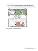
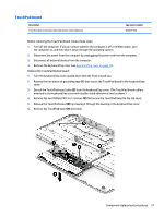
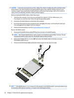
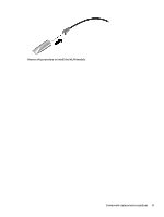
Battery, Connector board, Reverse this procedure to install the TouchPad board.
 |
View all HP Chromebook 11-2200 manuals
Add to My Manuals
Save this manual to your list of manuals |
Page 34 highlights
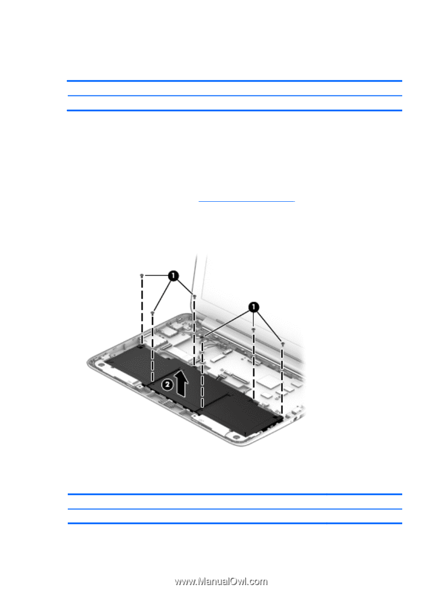
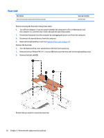
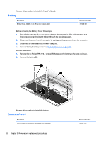
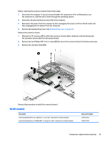
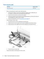
Reverse this procedure to install the TouchPad board. Battery Description Battery (3-cell, 36-WHr, 3.25-AHr, Li-ion; includes cable) Spare part number 767068-001 Before removing the battery, follow these steps: 1. Turn off the computer. If you are unsure whether the computer is off or in Hibernation, turn the computer on, and then shut it down through the operating system. 2. Disconnect the power from the computer by unplugging the power cord from the computer. 3. Disconnect all external devices from the computer. 4. Remove the keyboard/top cover (see Keyboard/top cover on page 21). Remove the battery: 1. Remove the six Phillips PM1.9×4.2 screws (2) that secure the battery to the base enclosure. 2. Remove the battery (2). Reverse this procedure to install the battery. Connector board Description Connector board (includes SD Card Reader slot and cable) 28 Chapter 5 Removal and replacement procedures Spare part number 783087-001
-
 1
1 -
2
-
3
-
4
-
5
-
6
-
7
-
8
-
9
-
10
-
11
-
12
-
13
-
14
-
15
-
16
-
17
-
18
-
19
-
20
-
21
-
22
-
23
-
24
-
25
-
26
-
27
-
28
-
 29
29 -
 30
30 -
 31
31 -
 32
32 -
 33
33 -
 34
34 -
 35
35 -
 36
36 -
 37
37 -
 38
38 -
 39
39 -
40
-
41
-
42
-
43
-
44
-
45
-
46
-
47
-
48
-
49
-
50
-
51
-
52
-
53
-
54
-
55
-
56
-
57
 |
 |