HP Chromebook 13 G1 Maintenance and Service Guide - Page 37
Display assembly, IMPORTANT
 |
View all HP Chromebook 13 G1 manuals
Add to My Manuals
Save this manual to your list of manuals |
Page 37 highlights
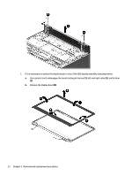
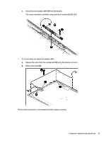
Display assembly Description Bezel Panel (FHD) Panel (QHD+) Hinge kit (includes left and right hinges and caps) Cable (LVDS QHD+) HD camera/microphone module Display enclosure (includes antennas, rubber padding, and shielding) Spare part number 859529-001 859533-001 859534-001 859530-001 861672-001 861692-001 859532-001 IMPORTANT: Make special note of each screw and screw lock size and location during removal and replacement. Before removing the display assembly, follow these steps: 1. Turn off the computer. If you are unsure whether the computer is off or in Hibernation, turn the computer on, and then shut it down through the operating system. 2. Disconnect the power from the computer by unplugging the power cord from the computer. 3. Disconnect all external devices from the computer. 4. Remove the two computer feet and base enclosure (see Computer feet and base enclosure on page 19). 5. Remove the battery (see Battery on page 21). 6. Remove the heat sink (see Heat sink on page 21). 7. Remove the WLAN module (see WLAN module on page 23). 8. Remove the system board (see System board on page 25). 9. Remove the speakers (see Speakers on page 27). 10. Remove the SD card reader board (see SD card reader board on page 28). Remove the display assembly: 1. Remove the two screws from the right hinge and the two screws from the left hinge (1), and then remove the display assembly (2). Component replacement procedures 31
-
 1
1 -
2
-
3
-
4
-
5
-
6
-
7
-
8
-
9
-
10
-
11
-
12
-
13
-
14
-
15
-
16
-
17
-
18
-
19
-
20
-
21
-
22
-
23
-
24
-
25
-
26
-
27
-
28
-
29
-
30
-
31
-
 32
32 -
 33
33 -
 34
34 -
 35
35 -
 36
36 -
 37
37 -
 38
38 -
 39
39 -
 40
40 -
 41
41 -
 42
42 -
43
-
44
-
45
-
46
-
47
-
48
 |
 |
