HP Cisco MDS 8/24c Cisco MDS 8Gb Fabric Switch for HP BladeSystem c-Class Inst - Page 2
Switch connection identification, External ports, Installing the switch
 |
View all HP Cisco MDS 8/24c manuals
Add to My Manuals
Save this manual to your list of manuals |
Page 2 highlights
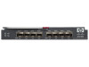
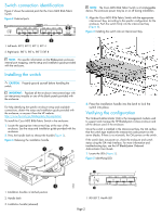
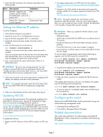
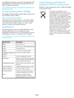
Switch connection identification Figure 2 shows the external ports for the Cisco MDS 8Gb Fabric Switch. Figure 2 External ports NOTE: The Cisco MDS 8Gb Fabric Switch is a hot-pluggable device. The enclosure power may be on or off during installation. 3. Align the Cisco MDS 8Gb Fabric Switch with the appropriate interconnect bay, according to the specific configuration for the enclosure. Push the switch firmly into the interconnect bay (Figure 4). Figure 4 Installing the switch into an interconnect bay 196996 1 2 1. Left bank: EXT1, EXT 2, EXT 3, EXT 4 2. Right bank: EXT 5, EXT 6, EXT 7, EXT 8 NOTE: For specific information on the Bladesystem enclosure internal port mapping, see the setup and installation guide provided with the enclosure. Installing the switch CAUTION: Properly ground yourself before handling the switch. IMPORTANT: Populate all the enclosure interconnect bays with an interconnect module or one of the blank panels provided with the enclosure. For help identifying the specific enclosure setup and available connections, obtain the setup and installation guide provided with the enclosure, or access it from the HP website: http://www.hp.com/go/bladesystem/documentation To install the Cisco MDS 8Gb Fabric Switch in the enclosure: 1. Locate the appropriate interconnect bay at the rear of the enclosure. See the setup and installation guide provided with the enclosure. 2. Press the handle latch to release the handle (Figure 3). Figure 3 Releasing the installation handle scale: 2/3" = 1" 1 2 20 19 18 17 EXT 7 EXT 6 EXT5 4 EXT 5 EXT 5 EXT 8 EXT 7 EXT 8 Cisco MDS 8Gb Fabric Switch 4. Press the installation handle into the latch to lock the switch into place. Verifying the configuration The Onboard Administrator (OA) is the management module used to support and manage the HP BladeSystem c-Class enclosure and all the devices used in the enclosure. Once the switch is installed in the interconnect bay, the OA verifies that the switch type matches the mezzanine cards present on the server blades. If there is no mismatch, the OA powers on the switch. If the switch does not power on, check the enclosure and switch status using the OA web interface. For more information and troubleshooting tips, see the HP BladeSystem Onboard Administrator User Guide. 1. Locate the LEDs (Figure 5). Figure 5 Identifying LEDs 1 ! 196991 196998 3 1. Installation handles in latched position 2. Handle latch 3. Installation handle (released) 2 1. UID LED 2. Health LED Page 2
-
 1
1 -
 2
2 -
 3
3 -
 4
4
 |
 |
