HP Cluster Platform Hardware Kits v2010 24 Node Cable Management Kit Installat - Page 10
Removing the Brackets to Repair a Damaged Cable
 |
View all HP Cluster Platform Hardware Kits v2010 manuals
Add to My Manuals
Save this manual to your list of manuals |
Page 10 highlights
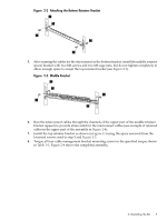
Figure 2-4 Completed 24 Node Cable Management Kit 3 2 4 1 5 6 1 7 The following list describes the callouts shown in Figure 2-4. 1. Mounting screws. 2. Right rack column. 3. Left rack column. 4. Top bracket. 5. Middle bracket. 6. Bottom bracket. 7. Example of retained InfiniBand cables in the upper part of the cable management kit. Note: You must install the entire 24 node cable management kit to provide proper strain relief for the InfiniBand cables. 2.2 Removing the Brackets to Repair a Damaged Cable Bring the component to an appropriate state for cable removal (refer to the HP Cluster Platform InfiniBand Interconnect Guide). NOTE: It is not necessary to remove all the pieces of the 24 node cable management kit to remove a cable for repair or replacement. 1. To remove a cable in the upper part of the assembly, remove the top retainer bracket. It is not necessary to remove the middle spacer or bottom bracket to remove a cable from the group of cables on top of the middle spacer bracket. Simply remove the top retainer bracket to allow access to the cables on the top portion of the middle spacer bracket. 2. To remove a lower cable, remove the bottom retainer bracket only. This will keep the cables retained in the upper position while the lower cable is removed and replaced. Use tape to keep the remaining and functioning cables in place to prevent damage while replacing a separate non-functioning cable. 2.3 Removing the 24 Node Cable Management Bracket Kit To remove the 24 Node Cable Management Bracket Kit, follow these steps: 10 Installing the Kit
-
 1
1 -
2
-
3
-
4
-
 5
5 -
 6
6 -
 7
7 -
 8
8 -
 9
9 -
 10
10 -
 11
11 -
 12
12
 |
 |
