HP Deskpro 6000 Compaq Reference Guide Deskpro 4000 and Deskpro 6000 Series of - Page 15
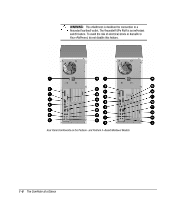
Minitower Rear Panel Components
 |
View all HP Deskpro 6000 manuals
Add to My Manuals
Save this manual to your list of manuals |
Page 15 highlights
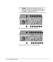
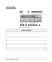
Ref. 1 2 3 4 5 6 7 8 9 : ; < = > ? @ A Minitower Rear Panel Components Connector Function Voltage Select Switch Switches voltage between 115V (U.S.) and 230V to match geographical requirements. Parallel Connector Connects a parallel device, such as a parallel printer. Network Status Lights Yellow link light turns on when network driver is properly loaded and system is physically connected to a network. Green activity light turns on when system detects network activity. Ethernet RJ-45 Connector Connects to an Ethernet network, using an RJ-45 cable. External Infrared Transceiver Connector Connects an optional external infrared transceiver. (Yellowcolored icon) Keyboard Connector Connects the keyboard. (Orange-colored icon) Headphone Connector Connects headphones. (CD-ROM drive models) Line-Out Audio Connector Connects an external amplifier (to power additional speakers) or a tape deck for recording. (CD-ROM drive models) Line-in Audio Connector Connects a device that supplies sound, such as a tape deck or CD player. (CD-ROM drive models) Microphone Connector Connects a microphone. (CD-ROM drive models; bluecolored icon) Mouse Connector Connects the mouse. (Green-colored icon) Serial Connectors Connects a serial device, such as a serial mouse or scanner. Universal Serial Bus (USB) Connectors Connects the computer to any USB peripheral while the computer is operating; are fully functional Plug and Play connectors. Ethernet AUI Connector Connects to an Ethernet network, using an AUI cable or an AUI to BNC transceiver. Monitor Connector Connects a monitor. NOTE: Your computer will include either a PCI or an AGP monitor connector, but not both. Power Cord Connects the computer to an electrical power outlet. Ultra-SCSI Connector Connects external SCSI devices. (Deskpro 6000 models) Reference Guide 1-9
-
 1
1 -
2
-
3
-
4
-
5
-
6
-
7
-
8
-
9
-
 10
10 -
 11
11 -
 12
12 -
 13
13 -
 14
14 -
 15
15 -
 16
16 -
 17
17 -
 18
18 -
 19
19 -
 20
20 -
21
-
22
-
23
-
24
-
25
-
26
-
27
-
28
-
29
-
30
-
31
-
32
-
33
-
34
-
35
-
36
-
37
-
38
-
39
-
40
-
41
-
42
-
43
-
44
-
45
-
46
-
47
-
48
-
49
-
50
-
51
-
52
-
53
-
54
-
55
-
56
-
57
-
58
-
59
-
60
-
61
-
62
-
63
-
64
-
65
-
66
-
67
-
68
-
69
-
70
-
71
-
72
-
73
-
74
-
75
-
76
-
77
-
78
-
79
-
80
-
81
-
82
-
83
-
84
-
85
-
86
-
87
-
88
-
89
-
90
-
91
-
92
-
93
-
94
-
95
-
96
-
97
-
98
-
99
-
100
-
101
-
102
-
103
-
104
-
105
-
106
-
107
-
108
-
109
-
110
-
111
-
112
-
113
-
114
-
115
-
116
-
117
-
118
-
119
-
120
-
121
-
122
-
123
-
124
-
125
-
126
-
127
-
128
-
129
-
130
-
131
-
132
-
133
-
134
-
135
-
136
-
137
-
138
-
139
-
140
-
141
-
142
-
143
-
144
-
145
-
146
-
147
-
148
-
149
-
150
-
151
-
152
-
153
-
154
-
155
-
156
-
157
-
158
-
159
-
160
-
161
-
162
-
163
-
164
-
165
-
166
-
167
-
168
-
169
-
170
-
171
-
172
-
173
-
174
-
175
-
176
-
177
-
178
-
179
-
180
-
181
-
182
-
183
-
184
-
185
-
186
-
187
-
188
-
189
-
190
-
191
-
192
-
193
-
194
-
195
-
196
-
197
-
198
-
199
-
200
-
201
-
202
-
203
-
204
-
205
-
206
-
207
-
208
-
209
-
210
-
211
-
212
-
213
-
214
-
215
-
216
-
217
-
218
-
219
-
220
-
221
-
222
-
223
-
224
-
225
-
226
-
227
-
228
-
229
-
230
-
231
-
232
-
233
-
234
 |
 |