HP Dv7-3085dx HP Pavilion dv7 Entertainment PC - Maintenance and Service Guide - Page 72
Display assembly, Disconnect the wireless antenna cables from the WLAN module see
 |
View all HP Dv7-3085dx manuals
Add to My Manuals
Save this manual to your list of manuals |
Page 72 highlights
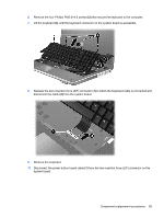
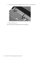
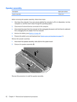
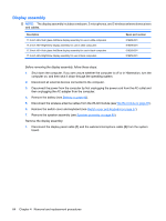
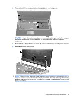
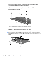
Display assembly NOTE: The display assembly includes a webcam, 2 microphones, and 2 wireless antenna transceivers and cables. Description 17.3-inch HD+ flush glass AntiGlare display assembly for use in white computers 17.3-inch HD+ BrightView display assembly for use in white computers 17.3-inch HD+ flush glass AntiGlare display assembly for use in black computers 17.3-inch HD+ BrightView display assembly for use in black computers Spare part number 516296-001 516295-001 519260-001 519259-001 Before removing the display assembly, follow these steps: 1. Shut down the computer. If you are unsure whether the computer is off or in Hibernation, turn the computer on, and then shut it down through the operating system. 2. Disconnect all external devices connected to the computer. 3. Disconnect the power from the computer by first unplugging the power cord from the AC outlet and then unplugging the AC adapter from the computer. 4. Remove the battery (see Battery on page 43). 5. Disconnect the wireless antenna cables from the WLAN module (see WLAN module on page 50). 6. Remove the switch cover and keyboard (see Switch cover and keyboard on page 57). 7. Remove the speaker assembly (see Speaker assembly on page 62). Remove the display assembly: 1. Disconnect the display panel cable (1) and the webcam/microphone cable (2) from the system board. 64 Chapter 4 Removal and replacement procedures
-
 1
1 -
2
-
3
-
4
-
5
-
6
-
7
-
8
-
9
-
10
-
11
-
12
-
13
-
14
-
15
-
16
-
17
-
18
-
19
-
20
-
21
-
22
-
23
-
24
-
25
-
26
-
27
-
28
-
29
-
30
-
31
-
32
-
33
-
34
-
35
-
36
-
37
-
38
-
39
-
40
-
41
-
42
-
43
-
44
-
45
-
46
-
47
-
48
-
49
-
50
-
51
-
52
-
53
-
54
-
55
-
56
-
57
-
58
-
59
-
60
-
61
-
62
-
63
-
64
-
65
-
66
-
 67
67 -
 68
68 -
 69
69 -
 70
70 -
 71
71 -
 72
72 -
 73
73 -
 74
74 -
 75
75 -
 76
76 -
 77
77 -
78
-
79
-
80
-
81
-
82
-
83
-
84
-
85
-
86
-
87
-
88
-
89
-
90
-
91
-
92
-
93
-
94
-
95
-
96
-
97
-
98
-
99
-
100
-
101
-
102
-
103
-
104
-
105
-
106
-
107
-
108
-
109
-
110
-
111
-
112
-
113
-
114
-
115
-
116
-
117
-
118
-
119
-
120
-
121
-
122
-
123
-
124
-
125
-
126
-
127
-
128
-
129
-
130
-
131
-
132
-
133
-
134
-
135
-
136
-
137
-
138
-
139
-
140
-
141
-
142
-
143
-
144
-
145
-
146
-
147
-
148
-
149
-
150
-
151
-
152
-
153
-
154
-
155
-
156
-
157
-
158
-
159
-
160
-
161
-
162
-
163
-
164
 |
 |