HP ENVY 14t-1200 HP ENVY 14 Notebook PC - Maintenance and Service Guide - Page 65
from the fan surface. The power button board cable is, Release the power button board cable
 |
View all HP ENVY 14t-1200 manuals
Add to My Manuals
Save this manual to your list of manuals |
Page 65 highlights
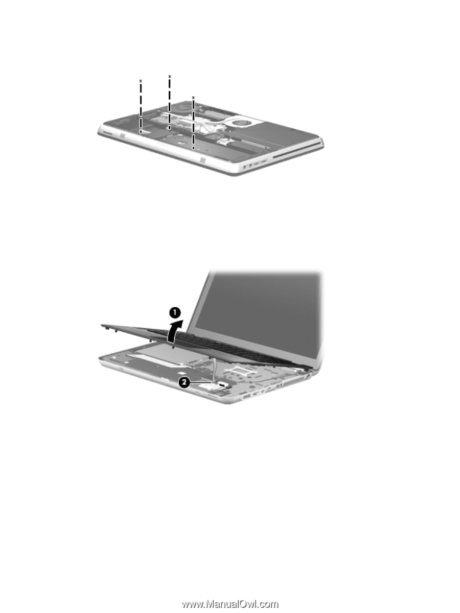
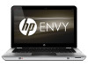
2. Remove the three Phillips PM2.0×3.0 screws that secure the top cover to the computer in the battery bay. 3. Turn the computer right side up, with the front toward you. 4. Open the computer as far as it will open. 5. Lift the front edge of top cover (1) until the TouchPad cable is accessible. 6. Release the ZIF connector to which the TouchPad cable is attached, and then disconnect the cable (2) from the system board. 7. Slide the top cover (1) forward until the power button board cable, keyboard cable, and keyboard light cable are accessible. 8. Release the power button board cable (2) from the fan surface. (The power button board cable is attached to the fan surface with double-sided tape.) 9. Disconnect the power button board cable (3) from the system board. 10. Release the ZIF connector to which the keyboard light cable is attached, and then disconnect the cable (4) from the system board. Component replacement procedures 57
-
 1
1 -
2
-
3
-
4
-
5
-
6
-
7
-
8
-
9
-
10
-
11
-
12
-
13
-
14
-
15
-
16
-
17
-
18
-
19
-
20
-
21
-
22
-
23
-
24
-
25
-
26
-
27
-
28
-
29
-
30
-
31
-
32
-
33
-
34
-
35
-
36
-
37
-
38
-
39
-
40
-
41
-
42
-
43
-
44
-
45
-
46
-
47
-
48
-
49
-
50
-
51
-
52
-
53
-
54
-
55
-
56
-
57
-
58
-
59
-
 60
60 -
 61
61 -
 62
62 -
 63
63 -
 64
64 -
 65
65 -
 66
66 -
 67
67 -
 68
68 -
 69
69 -
 70
70 -
71
-
72
-
73
-
74
-
75
-
76
-
77
-
78
-
79
-
80
-
81
-
82
-
83
-
84
-
85
-
86
-
87
-
88
-
89
-
90
-
91
-
92
-
93
-
94
-
95
-
96
-
97
-
98
-
99
-
100
-
101
-
102
-
103
-
104
-
105
-
106
-
107
-
108
-
109
-
110
-
111
-
112
-
113
-
114
-
115
-
116
 |
 |