HP ENVY 14t-1200 HP ENVY 14 Notebook PC - Maintenance and Service Guide - Page 87
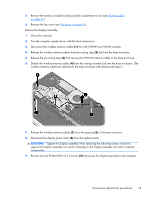
in the base enclosure., Disconnect the display panel cable
 |
View all HP ENVY 14t-1200 manuals
Add to My Manuals
Save this manual to your list of manuals |
Page 87 highlights
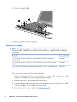
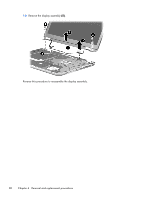
5. Remove the memory module/wireless module compartment cover (see WLAN module on page 47). 6. Remove the top cover (see Top cover on page 56). Remove the display assembly: 1. Close the computer. 2. Turn the computer upside down, with the front toward you. 3. Disconnect the wireless antenna cables (1) from the WWAN and WLAN modules. 4. Release the wireless antenna cables from the routing clips (2) built into the base enclosure. 5. Release the grounding tape (3) that secures the WWAN antenna cables to the base enclosure. 6. Detach the wireless antenna cables (4) from the routing channel built into the base enclosure. (The wireless antenna cables are attached to the base enclosure with double-sided tape.) 7. Release the wireless antenna cables (1) from the opening (2) in the base enclosure. 8. Disconnect the display panel cable (3) from the system board. CAUTION: Support the display assembly when removing the following screws. Failure to support the display assembly can result in damage to the display assembly and other computer components. 9. Remove the four Phillips PM2.5×4.0 screws (4) that secure the display assembly to the computer. Component replacement procedures 79
-
 1
1 -
2
-
3
-
4
-
5
-
6
-
7
-
8
-
9
-
10
-
11
-
12
-
13
-
14
-
15
-
16
-
17
-
18
-
19
-
20
-
21
-
22
-
23
-
24
-
25
-
26
-
27
-
28
-
29
-
30
-
31
-
32
-
33
-
34
-
35
-
36
-
37
-
38
-
39
-
40
-
41
-
42
-
43
-
44
-
45
-
46
-
47
-
48
-
49
-
50
-
51
-
52
-
53
-
54
-
55
-
56
-
57
-
58
-
59
-
60
-
61
-
62
-
63
-
64
-
65
-
66
-
67
-
68
-
69
-
70
-
71
-
72
-
73
-
74
-
75
-
76
-
77
-
78
-
79
-
80
-
81
-
 82
82 -
 83
83 -
 84
84 -
 85
85 -
 86
86 -
 87
87 -
 88
88 -
 89
89 -
 90
90 -
 91
91 -
 92
92 -
93
-
94
-
95
-
96
-
97
-
98
-
99
-
100
-
101
-
102
-
103
-
104
-
105
-
106
-
107
-
108
-
109
-
110
-
111
-
112
-
113
-
114
-
115
-
116
 |
 |
