HP ENVY 15-ah000 Maintenance and Service Guide - Page 69
The antennas are available using spare part number 812669-001., enclosure
 |
View all HP ENVY 15-ah000 manuals
Add to My Manuals
Save this manual to your list of manuals |
Page 69 highlights
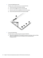
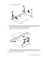
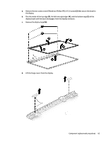
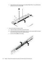
b. Remove the display hinges (3). 5. To remove the wireless antenna cables and transceivers, peel the transceivers from the enclosure (1), release the wireless antenna cables from the clips or tape (2) that secure the cables to the display enclosure, and then remove the antenna cables and transceivers (3). The antennas are available using spare part number 812669-001. 6. If replacing the display cover, be sure that the subcomponents (including the webcam/microphone module, the antenna receivers, and all associated cables and hardware) are transferred to the new cover. Reverse this procedure to install the display assembly. Component replacement procedures 61
-
 1
1 -
2
-
3
-
4
-
5
-
6
-
7
-
8
-
9
-
10
-
11
-
12
-
13
-
14
-
15
-
16
-
17
-
18
-
19
-
20
-
21
-
22
-
23
-
24
-
25
-
26
-
27
-
28
-
29
-
30
-
31
-
32
-
33
-
34
-
35
-
36
-
37
-
38
-
39
-
40
-
41
-
42
-
43
-
44
-
45
-
46
-
47
-
48
-
49
-
50
-
51
-
52
-
53
-
54
-
55
-
56
-
57
-
58
-
59
-
60
-
61
-
62
-
63
-
 64
64 -
 65
65 -
 66
66 -
 67
67 -
 68
68 -
 69
69 -
 70
70 -
 71
71 -
 72
72 -
 73
73 -
 74
74 -
75
-
76
-
77
-
78
-
79
-
80
-
81
-
82
-
83
-
84
-
85
-
86
-
87
-
88
-
89
-
90
-
91
-
92
-
93
-
94
-
95
-
96
-
97
-
98
-
99
-
100
-
101
-
102
 |
 |

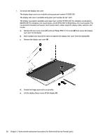
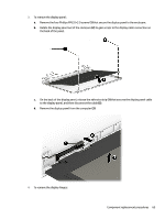
b.
Remove the display hinges
(3)
.
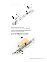
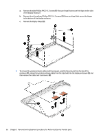
5.
To remove the wireless antenna cables and transceivers, peel the transceivers from the enclosure
(1)
,
release the wireless antenna cables from the clips or tape
(2)
that secure the cables to the display
enclosure, and then remove the antenna cables and transceivers
(3)
.
The antennas are available using spare part number 812669-001.
6.
If replacing the display cover, be sure that the subcomponents (including the webcam/microphone
module, the antenna receivers, and all associated cables and hardware) are transferred to the new cover.
Reverse this procedure to install the display assembly.
Component replacement procedures
61