HP ENVY 17-j150nr HP ENVY 17 Notebook PC HP ENVY TouchSmart m7 Notebook PC HP - Page 83
Power connector cable, Remove the Leap Motion module
 |
View all HP ENVY 17-j150nr manuals
Add to My Manuals
Save this manual to your list of manuals |
Page 83 highlights
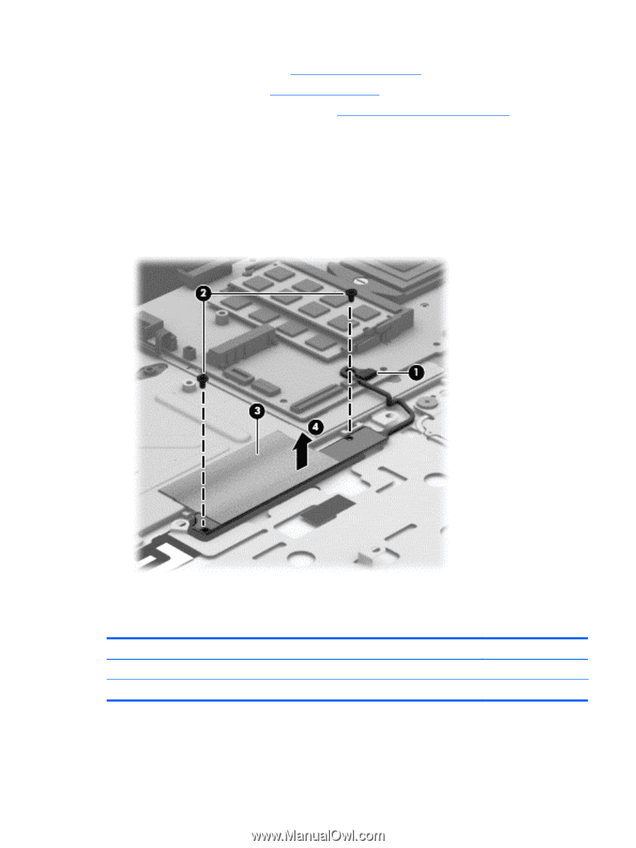
10. Remove the base enclosure (see Base enclosure on page 55). 11. Remove the USB board (see USB board on page 69). 12. Remove the fingerprint reader module (see Fingerprint reader board on page 71). Remove the Leap Motion module: 1. Disconnect the Leap Motion module cable (1) from the system board. 2. Remove the two Phillips PM1.5×2.5 screws (2) that secure the Leap Motion module to the top cover. 3. Detach the Leap Motion module grounding shield (3) from the top cover. (The Leap Motion grounding shield is attached to the top cover with double-sided adhesive.) 4. Remove the Leap Motion module (4). Reverse this procedure to install the Leap Motion module. Power connector cable Description For use only on computer models equipped with a graphics subsystem with discrete memory For use only on computer models equipped with a graphics subsystem with UMA memory Spare part number 720240-001 720241-001 Component replacement procedures 73
-
 1
1 -
2
-
3
-
4
-
5
-
6
-
7
-
8
-
9
-
10
-
11
-
12
-
13
-
14
-
15
-
16
-
17
-
18
-
19
-
20
-
21
-
22
-
23
-
24
-
25
-
26
-
27
-
28
-
29
-
30
-
31
-
32
-
33
-
34
-
35
-
36
-
37
-
38
-
39
-
40
-
41
-
42
-
43
-
44
-
45
-
46
-
47
-
48
-
49
-
50
-
51
-
52
-
53
-
54
-
55
-
56
-
57
-
58
-
59
-
60
-
61
-
62
-
63
-
64
-
65
-
66
-
67
-
68
-
69
-
70
-
71
-
72
-
73
-
74
-
75
-
76
-
77
-
 78
78 -
 79
79 -
 80
80 -
 81
81 -
 82
82 -
 83
83 -
 84
84 -
 85
85 -
 86
86 -
 87
87 -
 88
88 -
89
-
90
-
91
-
92
-
93
-
94
-
95
-
96
-
97
-
98
-
99
-
100
-
101
-
102
-
103
-
104
-
105
-
106
-
107
-
108
-
109
-
110
-
111
-
112
-
113
-
114
-
115
-
116
 |
 |