HP ENVY 17-j150nr HP ENVY 17 Notebook PC HP ENVY TouchSmart m7 Notebook PC HP - Page 98
Remove the 5 Phillips PM 2.5×3.0 screws
 |
View all HP ENVY 17-j150nr manuals
Add to My Manuals
Save this manual to your list of manuals |
Page 98 highlights
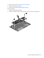
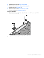
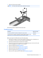
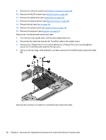
9. Remove the memory modules (see Memory modules on page 43). 10. Remove the WLAN module (see WLAN module on page 44). 11. Remove the optical drive (see Optical drive on page 46). 12. Remove the base enclosure (see Base enclosure on page 55). 13. Remove the fan (see Fan on page 74). 14. Remove the system board (see System board on page 76). 15. Remove the keyboard (see Keyboard on page 81). Remove the TouchPad button board and cable: 1. Turn the top cover upside down, with the back edge toward you. 2. Disconnect the cable that secures the TouchPad cable to the system board. 3. Remove the 5 Phillips PM 2.5×3.0 screws (1) and the 2 Phillips PM 2.5x3.0 screws (2) that secure the TouchPad button board to the top cover. 4. Lift up on the rear edge, slide backward, and then remove the TouchPad button board and cable (3). Reverse this procedure to install the TouchPad button board and cable. 88 Chapter 6 Removal and replacement procedures for Authorized Service Provider parts
-
 1
1 -
2
-
3
-
4
-
5
-
6
-
7
-
8
-
9
-
10
-
11
-
12
-
13
-
14
-
15
-
16
-
17
-
18
-
19
-
20
-
21
-
22
-
23
-
24
-
25
-
26
-
27
-
28
-
29
-
30
-
31
-
32
-
33
-
34
-
35
-
36
-
37
-
38
-
39
-
40
-
41
-
42
-
43
-
44
-
45
-
46
-
47
-
48
-
49
-
50
-
51
-
52
-
53
-
54
-
55
-
56
-
57
-
58
-
59
-
60
-
61
-
62
-
63
-
64
-
65
-
66
-
67
-
68
-
69
-
70
-
71
-
72
-
73
-
74
-
75
-
76
-
77
-
78
-
79
-
80
-
81
-
82
-
83
-
84
-
85
-
86
-
87
-
88
-
89
-
90
-
91
-
92
-
 93
93 -
 94
94 -
 95
95 -
 96
96 -
 97
97 -
 98
98 -
 99
99 -
 100
100 -
 101
101 -
 102
102 -
 103
103 -
104
-
105
-
106
-
107
-
108
-
109
-
110
-
111
-
112
-
113
-
114
-
115
-
116
 |
 |
