HP ENVY 17-u000 Maintenance and Service Guide - Page 49
System board, RTC battery see
 |
View all HP ENVY 17-u000 manuals
Add to My Manuals
Save this manual to your list of manuals |
Page 49 highlights
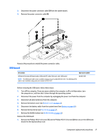
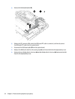
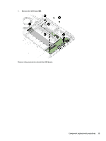
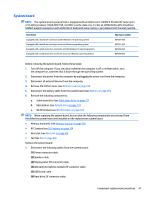
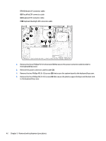
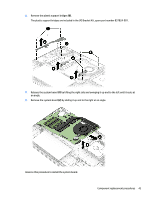
System board NOTE: The system board spare part kit is equipped with an Intel Core i7-6500U 2.50-GHz (SC turbo up to 3.10-GHz) processor (1600-MHz FSB, 4.0-MB L3 cache, dual core, 15-W), an nVIDIA N16S-GTR-S (GeForce 940MX) graphics subsystem with 2048-MB of dedicated video memory, and replacement thermal material. Description Equipped with a hard drive connector and the Windows 10 operating system Equipped with a hard drive connector and a non-Windows operating system Equipped with a solid-state drive connector and the Windows 10 operating system Equipped with a solid-state drive connector and a non-Windows operating system Spare part number 857297-601 857297-001 857298-601 857298-001 Before removing the system board, follow these steps: 1. Turn off the computer. If you are unsure whether the computer is off or in Hibernation, turn the computer on, and then shut it down through the operating system. 2. Disconnect the power from the computer by unplugging the power cord from the computer. 3. Disconnect all external devices from the computer. 4. Remove the bottom cover (see Bottom cover on page 24). 5. Disconnect the battery cable from the system board (see Battery on page 26). 6. Remove the following components: a. Solid-state drive (see Solid-state drive on page 27) b. Optical drive (see Optical drive on page 34) c. WLAN module (see WLAN module on page 32) NOTE: When replacing the system board, be sure that the following components are removed from the defective system board and installed on the replacement system board: ● Memory module(s) (see Memory module on page 29) ● RTC battery (see RTC battery on page 30) ● Heat sink (see Heat sink on page 44) ● Fan (see Fan on page 46) Remove the system board: 1. Disconnect the following cables from the system board: (1) Power connector cable (2) Speaker cable (3) Display panel ZIF connector cable (4) Webcam/microphone module ZIF connector cable (5) USB board cable (6) Hard drive ZIF connector cable Component replacement procedures 41
-
 1
1 -
2
-
3
-
4
-
5
-
6
-
7
-
8
-
9
-
10
-
11
-
12
-
13
-
14
-
15
-
16
-
17
-
18
-
19
-
20
-
21
-
22
-
23
-
24
-
25
-
26
-
27
-
28
-
29
-
30
-
31
-
32
-
33
-
34
-
35
-
36
-
37
-
38
-
39
-
40
-
41
-
42
-
43
-
 44
44 -
 45
45 -
 46
46 -
 47
47 -
 48
48 -
 49
49 -
 50
50 -
 51
51 -
 52
52 -
 53
53 -
 54
54 -
55
-
56
-
57
-
58
-
59
-
60
-
61
-
62
-
63
-
64
-
65
-
66
-
67
-
68
-
69
-
70
-
71
-
72
-
73
-
74
-
75
-
76
 |
 |
