HP ENVY TouchSmart m6-k015dx HP ENVY m6 Sleekbook HP ENVY Touchsmart m6 SleekB - Page 48
RJ-45 module cover
 |
View all HP ENVY TouchSmart m6-k015dx manuals
Add to My Manuals
Save this manual to your list of manuals |
Page 48 highlights
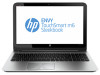
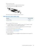
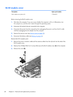
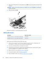
RJ-45 module cover Description RJ-45 module cover (plastics kit) Spare part number 727464-001 Before removing the RJ-45 module cover: 1. Shut down the computer. If you are unsure whether the computer is off or in Hibernation, turn the computer on, and then shut it down through the operating system. 2. Disconnect all external devices connected to the computer. 3. Disconnect the power from the computer by first unplugging the power cord from the AC outlet and then unplugging the AC adapter from the computer. 4. Remove the service cover (see Service cover on page 30). 5. Disconnect the battery cable (see Battery on page 32). Remove the RJ-45 module cover: 1. Remove the power connector cable and the antenna cables from the clip built into the side of the RJ-45 module cover. 2. Remove the 2 Phillips PM2.5×5.5 screws that secure the RJ-45 module cover (1) to the computer. 3. Remove the cover (2). 40 Chapter 4 Removal and replacement procedures
-
 1
1 -
2
-
3
-
4
-
5
-
6
-
7
-
8
-
9
-
10
-
11
-
12
-
13
-
14
-
15
-
16
-
17
-
18
-
19
-
20
-
21
-
22
-
23
-
24
-
25
-
26
-
27
-
28
-
29
-
30
-
31
-
32
-
33
-
34
-
35
-
36
-
37
-
38
-
39
-
40
-
41
-
42
-
 43
43 -
 44
44 -
 45
45 -
 46
46 -
 47
47 -
 48
48 -
 49
49 -
 50
50 -
 51
51 -
 52
52 -
 53
53 -
54
-
55
-
56
-
57
-
58
-
59
-
60
-
61
-
62
-
63
-
64
-
65
-
66
-
67
-
68
-
69
-
70
-
71
-
72
-
73
-
74
-
75
-
76
-
77
-
78
-
79
-
80
-
81
-
82
-
83
-
84
-
85
-
86
-
87
-
88
-
89
-
90
-
91
-
92
-
93
-
94
-
95
-
96
 |
 |
