HP EVA P6000 HP Controller Enclosure Midplane Replacement Instructions (593095
HP EVA P6000 Manual
 |
View all HP EVA P6000 manuals
Add to My Manuals
Save this manual to your list of manuals |
HP EVA P6000 manual content summary:
- HP EVA P6000 | HP Controller Enclosure Midplane Replacement Instructions (593095 - Page 1
, or see erroneous LED indications on the following components that you know are good, then you might suspect a problem with the midplane board: • Battery module • Fan module • Array controller • Management module • Power supply module • Riser assembly • LED display • Power UID *593095-001* Page 1 - HP EVA P6000 | HP Controller Enclosure Midplane Replacement Instructions (593095 - Page 2
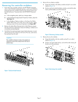
Power down the controller enclosure with HP P6000 Command View or the HP P6000 web-based operator control panel (WOCP). Powering down the controller enclosure also removes power from the disk enclosures. To power down with HP P6000 Command View: a. In the navigation pane, select your storage system - HP EVA P6000 | HP Controller Enclosure Midplane Replacement Instructions (593095 - Page 3
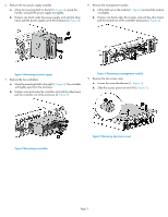
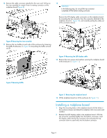
, and with the other hand, pull the module out of the controller enclosure (2, Figure 6). Figure 4 Removing a power supply . 7. Remove the two controllers. a. Move the mounting latch to the right (1, Figure 5). The controller will slightly eject from the enclosure. b. Position one hand under the - HP EVA P6000 | HP Controller Enclosure Midplane Replacement Instructions (593095 - Page 4
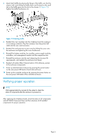
card. Pull up on the riser assembly to unseat it from its mating connector on the midplane board (Figure 8). 12. CAUTION: In the following step, do not pull the top connector completely off the bottom mating connector. Remove the LED display cable (2, Figure 11). Installing a midplane board 1. - HP EVA P6000 | HP Controller Enclosure Midplane Replacement Instructions (593095 - Page 5
bezel of the controller enclosure. Verifying proper operation NOTE: Wait approximately five minutes for the system to check the status of components after the enclosure is powered on. After replacing the midplane board, check the status of all components with HP P6000 Command View and the indicators
-
 1
1 -
 2
2 -
 3
3 -
 4
4 -
 5
5
 |
 |

HP Controller Enclosure
Midplane Replacement
Instructions
© Copyright 2009 Hewlett-Packard Development Company, L.P.
Second edition: May 2011
The information in this document is subject to change without notice.
Printed in Puerto Rico
www.hp.com
*593095-001*
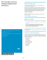
About this document
For the latest documentation, go to
h
t
tp://w
w
w
.hp
.co
m/su
ppo
r
t/
man
uals
, and select your product.
The information contained herein is subject to change without notice.
The only warranties for HP products and services are set forth in the
express warranty statements accompanying such products and services.
Nothing herein should be construed as constituting an additional
warranty. HP shall not be liable for technical or editorial errors or
omissions contained herein.
WARRANTY STATEMENT:
To obtain a copy of the warranty for this product, see the warranty
information website:
h
t
tp://w
w
w
.hp
.co
m/go/s
t
o
r
age
w
ar
r
an
t
y
Before you begin
Observe the following precaution when replacing the controller midplane.
CAUTION:
Parts can be damaged by electrostatic discharge. Use proper
anti-static protection. Refer to the documentation that shipped
with your system for additional information.
Your controller enclosure model may vary slightly from what is illustrated
in this document.
Verifying component failure
There are few active parts on the midplane board that can fail. If you
receive error messages, or see erroneous LED indications on the following
components that you know are good, then you might suspect a problem
with the midplane board:
•
Battery module
•
Fan module
•
Array controller
•
Management module
•
Power supply module
•
Riser assembly
•
LED display
•
Power UID
Page 1