HP EVA P6550 HP P6300/P6500 EVA Installation Guide (5697-2485, September 2013) - Page 75
Connecting the P63x0/P65x0 EVA to servers and switches, Fibre Channel
 |
View all HP EVA P6550 manuals
Add to My Manuals
Save this manual to your list of manuals |
Page 75 highlights
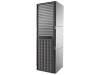
Connecting the P63x0/P65x0 EVA to servers and switches Fibre Channel You can connect the front end of the P63x0/P65x0 EVA FC controllers either to external Fibre Channel switches or directly to servers. The standard host port connectivity rule is to connect even controller ports to one fabric and odd controller ports to the other fabric. See Figure 60 (page 75) and Figure 62 (page 77) for front end connections with server-based management. See Figure 61 (page 76) and Figure 63 (page 78) for front end connections with array-based management. NOTE: The cabling diagrams in Figure 60 (page 75) through Figure 63 (page 78) require fabric connect mode, which is the default as shipped. The P63x0 is shown in these diagrams, but the port count and front-end cable placement is the same for the Fibre Channel version of the P65x0. Figure 60 Cabling the controller to front end component-Fibre Channel to switch detail view with server-based management 1. File server 2. Management server 3. Database server 4. Fiber channel switch 5. LED status indicators for cabling connections to disk enclosures. See Figure 55 (page 70) and Figure 59 (page 74) for cabling connections. Connecting the P63x0/P65x0 EVA to servers and switches 75
-
 1
1 -
2
-
3
-
4
-
5
-
6
-
7
-
8
-
9
-
10
-
11
-
12
-
13
-
14
-
15
-
16
-
17
-
18
-
19
-
20
-
21
-
22
-
23
-
24
-
25
-
26
-
27
-
28
-
29
-
30
-
31
-
32
-
33
-
34
-
35
-
36
-
37
-
38
-
39
-
40
-
41
-
42
-
43
-
44
-
45
-
46
-
47
-
48
-
49
-
50
-
51
-
52
-
53
-
54
-
55
-
56
-
57
-
58
-
59
-
60
-
61
-
62
-
63
-
64
-
65
-
66
-
67
-
68
-
69
-
 70
70 -
 71
71 -
 72
72 -
 73
73 -
 74
74 -
 75
75 -
 76
76 -
 77
77 -
 78
78 -
 79
79 -
 80
80 -
81
-
82
 |
 |
