HP EVA P6550 HP Controller Enclosure Cache DIMM Replacement Instructions (5697 - Page 2
Verifying component failure, Check status using HP P6000 Command View
 |
View all HP EVA P6550 manuals
Add to My Manuals
Save this manual to your list of manuals |
Page 2 highlights
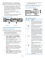
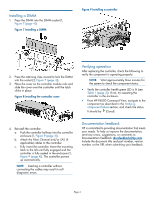
When replacing a DIMM, it is important that you upgrade the firmware before you install the DIMM. Failure to do so results in failure of the array to boot. • Alloy (gray)-colored latches on components like the controller indicates that the component is warm-swappable. Halt the I/O of a controller being serviced with HP P6000 Command View before removing this component. • There are two controllers at the rear of the controller enclosure. See Figure 1 (page 2) for the locations. • Your controller enclosure model may vary slightly from what is illustrated in this document. Figure 1 Controller locations 1. Controller 1 2. Controller 2 Verifying component failure Use the following methods to verify component failure: • Analyze any failure messages received. HP Insight Remote Support Software provides a recommended fault monitoring solution. • Check status using HP P6000 Command View: 1. In the navigation pane, select Storage system→Hardware→Controller enclosure and then select a controller. 2. The status is displayed in the Memory section and the Condition/State section. When a DIMM fails, the status in the Memory section could show a memory amount inconsistent with the amount known to be installed. The Cache state in the Condition/State section could show an operational state of (Failed) to indicate an improperly seated DIMM or a fault that requires a DIMM replacement. 3. To help identify the correct controller, click Locate→Locate On. This causes the blue UID indicator to light on the controller module at the rear of the controller enclosure. 4. View the controller event log to determine which DIMM has failed. • Observe the controller status LEDs as shown in Figure 2 (page 2) and Table 1 (page 2). Figure 2 Controller status LEDs Table 1 Controller status LEDs Item LED 1 2 3 4 MEZZ Indication Blue LED used to identify a specific controller module within the enclosure or the iSCSI or iSCSI/FCoE module (P63x0/P65x0 EVA only) within the controller. Green LED indicates controller health. LED flashes green during boot and becomes solid green after boot. Flashing amber indicates a controller termination or the system is inoperative and attention is required. Solid amber indicates that the controller cannot reboot and should be replaced. If both the solid amber and solid blue LEDs are lit, the controller has completed a warm removal procedure, and can be safely swapped. Applicable to the P63x0/P65x0 EVA only. Amber LED indicates the iSCSI or iSCSI/FCoE module status that is communicated to the array controller. Slow flashing amber LED indicates an IP address conflict on the management port. Solid amber indicates an iSCSI or iSCSI/FCoE module critical error or shutdown. 5 Green LED indicates write-back cache status. Slow flashing green LED indicates standby power. Solid green LED indicates cache is good with normal AC power applied. 6 Amber LED indicates DIMM status. The LED is off when DIMM status is good. Slow flashing amber indicates DIMMs are being powered by battery (during AC power loss). Solid amber indicates a DIMM failure. Page 2
-
 1
1 -
 2
2 -
 3
3 -
 4
4
 |
 |
