HP EVA P6550 HP Controller Enclosure Battery Replacement Instructions (5697-13 - Page 2
Verifying component failure, Removing a battery module, Controller Enclosure Properties window.
 |
View all HP EVA P6550 manuals
Add to My Manuals
Save this manual to your list of manuals |
Page 2 highlights
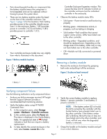
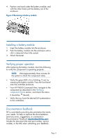
• Port-colored (purple) handles on components like the battery module means the component is hot-swappable and can be replaced without having to power the system down. • There are two battery modules under the bezel on the front of the controller enclosure. See Figure 1 (page 2) for the locations. Each battery provides power to the controller directly across from it in the enclosure. Battery 1 (B1) provides power to controller 2 (C2) and battery 2 (B2) provides power to controller 1 (C1). • Your controller enclosure model may vary slightly from what is illustrated in this document. Figure 1 Battery module locations Controller Enclosure Properties window. This causes the blue Unit ID indicator to blink on the controller enclosure (not the individual controller in the enclosure). • Observe the battery module status LEDs. ◦ Solid green-Power turned on and functioning properly ◦ Blinking green-Maintenance activity in progress, such as testing or charging ◦ Solid amber-Fault condition that cannot support cache activity. LUNs have failed over to the other controller. ◦ Blinking amber-Degraded condition, and should be replaced soon. Depending on the charge state of the battery, LUNs may or may not have failed over to the other controller. ◦ Off-Module not fully connected or powered down Removing a battery module 1. Remove the enclosure front bezel by grasping both ends and pulling it off the enclosure. Figure 2 Enclosure bezel removal 1. Battery 1 2. Battery 2 Verifying component failure Use the following methods to verify component failure: • Analyze any failure messages received. HP Insight Remote Support Software provides a recommended fault monitoring solution. • Verify the battery status using HP P6000 Command View: 1. In the navigation pane, select Storage system→Hardware→Controller enclosure. 2. In the contents pane, select the Power tab. The status is displayed in the Cache Battery fields. An operational state of (Failed) indicates a fault that can require a battery replacement. 3. To help identify the correct enclosure in the rack, select Locate→Locate On in the 2. Verify the correct battery module to replace. Battery 1 powers controller 2 and battery 2 powers controller 1. NOTE: If the battery amber LED is lit solid, the LUNs owned by the controller with the faulted battery have already failed over to the other controller. If the battery amber LED is blinking, the LUNs may or may not have failed over to the other controller, and if not, will fail over when the degraded battery is removed. 3. Grasp the handle on the battery module and pull it out a short distance. Page 2
-
 1
1 -
 2
2 -
 3
3
 |
 |
