HP EliteBook 830 Maintenance and Service Guide - Page 50
WWAN module, Remove the Phillips M2.0 × 2.5 screw
 |
View all HP EliteBook 830 manuals
Add to My Manuals
Save this manual to your list of manuals |
Page 50 highlights
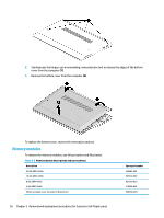
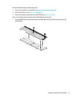
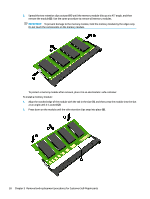
2. Remove the Phillips M2.0 × 2.5 screw (2), and then remove the WLAN module (3). NOTE: Models have either one or two WLAN antennas. On models with two antennas, the #1 white WLAN antenna cable connects to the WLAN module #1 Main terminal. The #2 black WLAN antenna cable connects to the WLAN module #1 Aux terminal. 3. If the WLAN antenna is not connected to the terminal on the WLAN module, install a protective sleeve on the antenna connector, as shown in the following illustration. Reverse this procedure to install the WLAN module. WWAN module To remove the WWAN module, use this procedure and illustration. 40 Chapter 5 Removal and replacement procedures for Customer Self-Repair parts
-
 1
1 -
2
-
3
-
4
-
5
-
6
-
7
-
8
-
9
-
10
-
11
-
12
-
13
-
14
-
15
-
16
-
17
-
18
-
19
-
20
-
21
-
22
-
23
-
24
-
25
-
26
-
27
-
28
-
29
-
30
-
31
-
32
-
33
-
34
-
35
-
36
-
37
-
38
-
39
-
40
-
41
-
42
-
43
-
44
-
 45
45 -
 46
46 -
 47
47 -
 48
48 -
 49
49 -
 50
50 -
 51
51 -
 52
52 -
 53
53 -
 54
54 -
 55
55 -
56
-
57
-
58
-
59
-
60
-
61
-
62
-
63
-
64
-
65
-
66
-
67
-
68
-
69
-
70
-
71
-
72
-
73
-
74
-
75
-
76
-
77
-
78
-
79
-
80
-
81
-
82
-
83
-
84
-
85
-
86
-
87
-
88
-
89
-
90
-
91
-
92
-
93
-
94
-
95
-
96
-
97
-
98
-
99
-
100
-
101
-
102
-
103
-
104
-
105
-
106
-
107
-
108
-
109
-
110
-
111
-
112
-
113
-
114
 |
 |

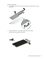
2.
Remove the Phillips M2.0 × 2.5 screw
(2)
, and then remove the WLAN module
(3)
.
NOTE:
Models have either one or two WLAN antennas. On models with two antennas, the #1 white
WLAN antenna cable connects to the WLAN module #1 Main terminal. The #2 black WLAN antenna cable
connects to the WLAN module #1 Aux terminal.
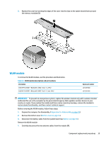
3.
If the WLAN antenna is not connected to the terminal on the WLAN module, install a protective sleeve on
the antenna connector, as shown in the following illustration.
Reverse this procedure to install the WLAN module.
WWAN module
To remove the WWAN module, use this procedure and illustration.
40
Chapter 5
Removal and replacement procedures for Customer Self-Repair parts