HP Envy 17-1006tx HP ENVY 17 - Maintenance and Service Guide - Page 68
System board, When replacing the system board
 |
View all HP Envy 17-1006tx manuals
Add to My Manuals
Save this manual to your list of manuals |
Page 68 highlights
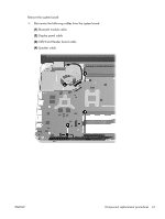
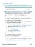
System board Description System board (includes 1 GB of discrete graphics subsystem memory and replacement thermal material) Spare part number 603771-001 Before removing the system board, follow these steps: 1. Shut down the computer. If you are unsure whether the computer is off or in Hibernation, turn the computer on, and then shut it down through the operating system. 2. Disconnect all external devices connected to the computer. 3. Disconnect the power from the computer by first unplugging the power cord from the AC outlet and then unplugging the AC adapter from the computer. 4. Remove the battery (see Battery on page 37), and then remove the following components: a. Hard drives (see Primary hard drive on page 38 and see Secondary hard drive on page 44) b. memory module compartment cover (see Memory module on page 42) c. Keyboard (see Keyboard on page 50) d. Top cover (see Top cover on page 52) e. Optical drive (see Optical drive on page 57) When replacing the system board, be sure that the following components are removed from the defective system board and installed on the replacement system board: ● RTC battery (see RTC battery on page 41) ● Memory modules (see Memory module on page 42) ● WLAN module (see WLAN module on page 48) ● Fan/heat sink assembly (see Fan/heat sink assembly on page 64) ● Processor (see Processor on page 66) 60 Chapter 4 Removal and replacement procedures ENWW
-
 1
1 -
2
-
3
-
4
-
5
-
6
-
7
-
8
-
9
-
10
-
11
-
12
-
13
-
14
-
15
-
16
-
17
-
18
-
19
-
20
-
21
-
22
-
23
-
24
-
25
-
26
-
27
-
28
-
29
-
30
-
31
-
32
-
33
-
34
-
35
-
36
-
37
-
38
-
39
-
40
-
41
-
42
-
43
-
44
-
45
-
46
-
47
-
48
-
49
-
50
-
51
-
52
-
53
-
54
-
55
-
56
-
57
-
58
-
59
-
60
-
61
-
62
-
 63
63 -
 64
64 -
 65
65 -
 66
66 -
 67
67 -
 68
68 -
 69
69 -
 70
70 -
 71
71 -
 72
72 -
 73
73 -
74
-
75
-
76
-
77
-
78
-
79
-
80
-
81
-
82
-
83
-
84
-
85
-
86
-
87
-
88
-
89
-
90
-
91
-
92
-
93
-
94
-
95
-
96
-
97
-
98
-
99
-
100
-
101
-
102
-
103
-
104
-
105
-
106
-
107
-
108
-
109
-
110
-
111
-
112
-
113
-
114
-
115
-
116
 |
 |
