HP Evo n1000v Maintenance and Service Guide - Page 109
Disassembly Sequence Chart
 |
View all HP Evo n1000v manuals
Add to My Manuals
Save this manual to your list of manuals |
Page 109 highlights
Removal and Replacement Procedures 5.2 Disassembly Sequence Chart Use the following chart to determine the section number to be referenced when removing computer components. Section 5.3 5.4 5.5 5.6 5.7 5.8 5.9 5.10 5.11 5.12 5.13 5.14 5.15 Disassembly Sequence Chart Description Preparing the computer for disassembly Battery pack Optical drive Hard drive Computer feet Memory expansion board Mini PCI communications board Disk cell RTC battery Connector cover LED cover Keyboard Heat spreader Processor Display Palm rest Diskette drive # of Screws Removed 0 2 1 to remove the hard drive 4 to remove the hard drive from hard drive bracket 0 1 1 0 2 2 0 7 0 6 6 3 Maintenance and Service Guide 5-3
-
 1
1 -
2
-
3
-
4
-
5
-
6
-
7
-
8
-
9
-
10
-
11
-
12
-
13
-
14
-
15
-
16
-
17
-
18
-
19
-
20
-
21
-
22
-
23
-
24
-
25
-
26
-
27
-
28
-
29
-
30
-
31
-
32
-
33
-
34
-
35
-
36
-
37
-
38
-
39
-
40
-
41
-
42
-
43
-
44
-
45
-
46
-
47
-
48
-
49
-
50
-
51
-
52
-
53
-
54
-
55
-
56
-
57
-
58
-
59
-
60
-
61
-
62
-
63
-
64
-
65
-
66
-
67
-
68
-
69
-
70
-
71
-
72
-
73
-
74
-
75
-
76
-
77
-
78
-
79
-
80
-
81
-
82
-
83
-
84
-
85
-
86
-
87
-
88
-
89
-
90
-
91
-
92
-
93
-
94
-
95
-
96
-
97
-
98
-
99
-
100
-
101
-
102
-
103
-
 104
104 -
 105
105 -
 106
106 -
 107
107 -
 108
108 -
 109
109 -
 110
110 -
 111
111 -
 112
112 -
 113
113 -
 114
114 -
115
-
116
-
117
-
118
-
119
-
120
-
121
-
122
-
123
-
124
-
125
-
126
-
127
-
128
-
129
-
130
-
131
-
132
-
133
-
134
-
135
-
136
-
137
-
138
-
139
-
140
-
141
-
142
-
143
-
144
-
145
-
146
-
147
-
148
-
149
-
150
-
151
-
152
-
153
-
154
-
155
-
156
-
157
-
158
-
159
-
160
-
161
-
162
-
163
-
164
-
165
-
166
-
167
-
168
-
169
-
170
-
171
-
172
-
173
-
174
-
175
-
176
-
177
-
178
-
179
-
180
-
181
-
182
-
183
-
184
-
185
-
186
-
187
-
188
-
189
-
190
-
191
-
192
-
193
-
194
-
195
-
196
-
197
-
198
-
199
-
200
-
201
-
202
-
203
-
204
-
205
-
206
-
207
-
208
-
209
-
210
-
211
-
212
-
213
-
214
-
215
-
216
-
217
-
218
-
219
 |
 |
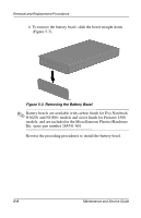
Removal and Replacement Procedures
Maintenance and Service Guide
5–3
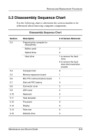
5.2 Disassembly Sequence Chart
Use the following chart to determine the section number to be
referenced when removing computer components.
Disassembly Sequence Chart
Section
Description
# of Screws Removed
5.3
Preparing the computer for
disassembly
Battery pack
0
Optical drive
2
Hard drive
1 to remove the hard
drive
4 to remove the hard
drive from hard drive
bracket
5.4
Computer feet
0
5.5
Memory expansion board
1
5.6
Mini PCI communications board
1
5.7
Disk cell RTC battery
0
5.8
Connector cover
2
5.9
LED cover
2
5.10
Keyboard
0
5.11
Heat spreader
7
5.12
Processor
0
5.13
Display
6
5.14
Palm rest
6
5.15
Diskette drive
3