HP Evo n1000v Maintenance and Service Guide - Page 152
Display Release Assembly
 |
View all HP Evo n1000v manuals
Add to My Manuals
Save this manual to your list of manuals |
Page 152 highlights
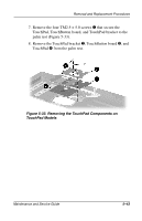
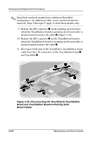
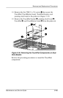
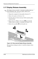
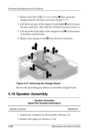
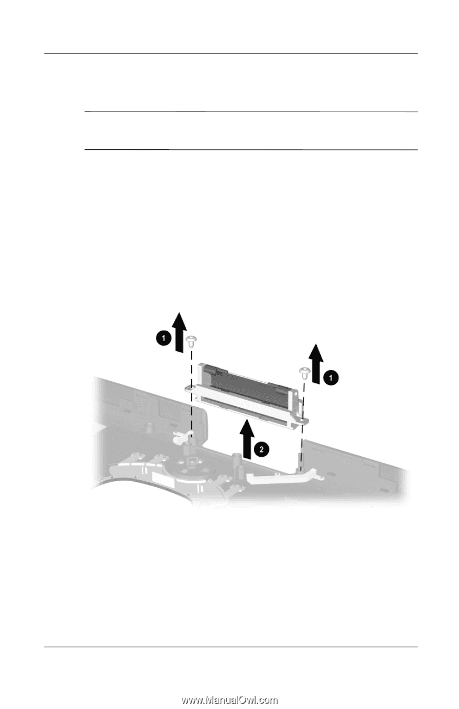
Removal and Replacement Procedures 5.17 Display Release Assembly ✎ The display release assembly is included in the Miscellaneous Plastics/Hardware Kit, spare part number 285541-001. 1. Prepare the computer for disassembly (Section 5.3). 2. Remove the palm rest (Section 5.14). 3. Turn the palm rest bottom side up with the speaker grilles facing forward. 4. Remove the two TM2.5 × 5.0 screws 1 that secure the display release assembly to the palm rest (Figure 5-36). 5. Remove the assembly 2 from the palm rest. Figure 5-36. Removing the Display Release Assembly Reverse the preceding procedures to install the display release assembly. 5-46 Maintenance and Service Guide
-
 1
1 -
2
-
3
-
4
-
5
-
6
-
7
-
8
-
9
-
10
-
11
-
12
-
13
-
14
-
15
-
16
-
17
-
18
-
19
-
20
-
21
-
22
-
23
-
24
-
25
-
26
-
27
-
28
-
29
-
30
-
31
-
32
-
33
-
34
-
35
-
36
-
37
-
38
-
39
-
40
-
41
-
42
-
43
-
44
-
45
-
46
-
47
-
48
-
49
-
50
-
51
-
52
-
53
-
54
-
55
-
56
-
57
-
58
-
59
-
60
-
61
-
62
-
63
-
64
-
65
-
66
-
67
-
68
-
69
-
70
-
71
-
72
-
73
-
74
-
75
-
76
-
77
-
78
-
79
-
80
-
81
-
82
-
83
-
84
-
85
-
86
-
87
-
88
-
89
-
90
-
91
-
92
-
93
-
94
-
95
-
96
-
97
-
98
-
99
-
100
-
101
-
102
-
103
-
104
-
105
-
106
-
107
-
108
-
109
-
110
-
111
-
112
-
113
-
114
-
115
-
116
-
117
-
118
-
119
-
120
-
121
-
122
-
123
-
124
-
125
-
126
-
127
-
128
-
129
-
130
-
131
-
132
-
133
-
134
-
135
-
136
-
137
-
138
-
139
-
140
-
141
-
142
-
143
-
144
-
145
-
146
-
 147
147 -
 148
148 -
 149
149 -
 150
150 -
 151
151 -
 152
152 -
 153
153 -
 154
154 -
 155
155 -
 156
156 -
 157
157 -
158
-
159
-
160
-
161
-
162
-
163
-
164
-
165
-
166
-
167
-
168
-
169
-
170
-
171
-
172
-
173
-
174
-
175
-
176
-
177
-
178
-
179
-
180
-
181
-
182
-
183
-
184
-
185
-
186
-
187
-
188
-
189
-
190
-
191
-
192
-
193
-
194
-
195
-
196
-
197
-
198
-
199
-
200
-
201
-
202
-
203
-
204
-
205
-
206
-
207
-
208
-
209
-
210
-
211
-
212
-
213
-
214
-
215
-
216
-
217
-
218
-
219
 |
 |
5–46
Maintenance and Service Guide
Removal and Replacement Procedures
5.17 Display Release Assembly
✎
The display release assembly is included in the Miscellaneous
Plastics/Hardware Kit, spare part number 285541-001.
1. Prepare the computer for disassembly (Section 5.3).
2. Remove the palm rest (Section 5.14).
3. Turn the palm rest bottom side up with the speaker grilles
facing forward.
4. Remove the two TM2.5 × 5.0 screws
1
that secure the
display release assembly to the palm rest (Figure 5-36).
5. Remove the assembly
2
from the palm rest.
Figure 5-36. Removing the Display Release Assembly
Reverse the preceding procedures to install the display release
assembly.