HP G60 549DX Service Guide - Page 55
module opposite the slot rises away from the computer. - black friday
 |
UPC - 884962661130
View all HP G60 549DX manuals
Add to My Manuals
Save this manual to your list of manuals |
Page 55 highlights
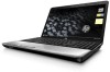
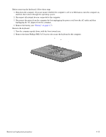
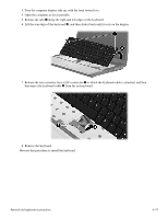
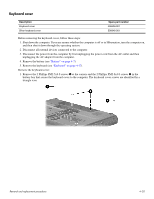
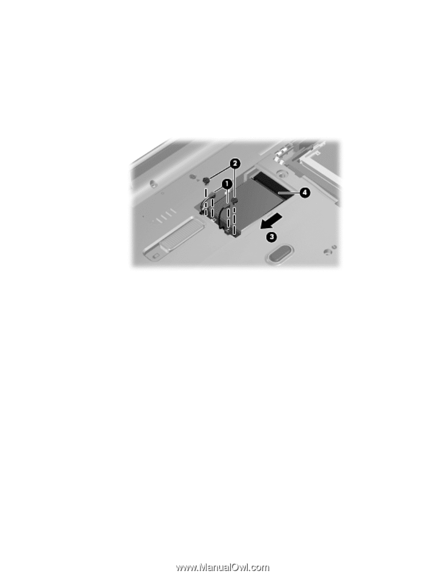
2. Disconnect the two antenna cables 1 from the wireless module. ✎ The black WLAN antenna cable is connected to the WLAN module "Main" terminal. The white WLAN antenna cable is connected to the WLAN module "Aux" terminal. 3. Remove the two Phillips PM2.0×4.0 screws 2 that secure the WLAN module to the computer. (The edge of the module opposite the slot rises away from the computer.) 4. Remove the WLAN module 3 by pulling the module away from the slot at an angle. ✎ WLAN modules are designed with a notch 4 to prevent incorrect insertion. Reverse this procedure to install the WLAN module. Removal and replacement procedures 4-16
-
 1
1 -
2
-
3
-
4
-
5
-
6
-
7
-
8
-
9
-
10
-
11
-
12
-
13
-
14
-
15
-
16
-
17
-
18
-
19
-
20
-
21
-
22
-
23
-
24
-
25
-
26
-
27
-
28
-
29
-
30
-
31
-
32
-
33
-
34
-
35
-
36
-
37
-
38
-
39
-
40
-
41
-
42
-
43
-
44
-
45
-
46
-
47
-
48
-
49
-
 50
50 -
 51
51 -
 52
52 -
 53
53 -
 54
54 -
 55
55 -
 56
56 -
 57
57 -
 58
58 -
 59
59 -
 60
60 -
61
-
62
-
63
-
64
-
65
-
66
-
67
-
68
-
69
-
70
-
71
-
72
-
73
-
74
-
75
-
76
-
77
-
78
-
79
-
80
-
81
-
82
-
83
-
84
-
85
-
86
-
87
-
88
-
89
-
90
-
91
-
92
-
93
-
94
-
95
-
96
-
97
-
98
-
99
-
100
-
101
-
102
-
103
-
104
-
105
-
106
-
107
-
108
-
109
-
110
-
111
-
112
-
113
-
114
-
115
-
116
-
117
-
118
-
119
-
120
-
121
-
122
-
123
-
124
-
125
-
126
-
127
-
128
-
129
-
130
-
131
-
132
-
133
-
134
 |
 |
Removal and replacement procedures
4–16
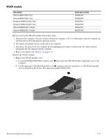
2. Disconnect the two antenna cables
1
from the wireless module.
✎
The black WLAN antenna cable is connected to the WLAN module “Main” terminal. The white WLAN antenna
cable is connected to the WLAN module “Aux” terminal.
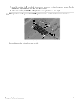
3.
Remove the two Phillips PM2.0×4.0 screws
2
that secure the WLAN module to the computer. (The edge of the
module opposite the slot rises away from the computer.)
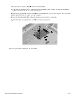
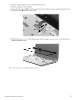
4. Remove the WLAN module
3
by pulling the module away from the slot at an angle.
✎
WLAN modules are designed with a notch
4
to prevent incorrect insertion.
Reverse this procedure to install the WLAN module.