HP G60 549DX Service Guide - Page 79
Remove the system board, from the base enclosure by sliding is up and to the right at an angle.
 |
UPC - 884962661130
View all HP G60 549DX manuals
Add to My Manuals
Save this manual to your list of manuals |
Page 79 highlights
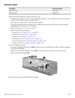
7. Release the power cable from the base enclosure 1. 8. Use the optical drive connector 2 to lift the right edge of the system board 3 until it rests at an angle. 9. Remove the system board 4 from the base enclosure by sliding is up and to the right at an angle. 10. Remove the optical extension board from the system board. Reverse this procedure to install the system board. Removal and replacement procedures 4-40
-
 1
1 -
2
-
3
-
4
-
5
-
6
-
7
-
8
-
9
-
10
-
11
-
12
-
13
-
14
-
15
-
16
-
17
-
18
-
19
-
20
-
21
-
22
-
23
-
24
-
25
-
26
-
27
-
28
-
29
-
30
-
31
-
32
-
33
-
34
-
35
-
36
-
37
-
38
-
39
-
40
-
41
-
42
-
43
-
44
-
45
-
46
-
47
-
48
-
49
-
50
-
51
-
52
-
53
-
54
-
55
-
56
-
57
-
58
-
59
-
60
-
61
-
62
-
63
-
64
-
65
-
66
-
67
-
68
-
69
-
70
-
71
-
72
-
73
-
 74
74 -
 75
75 -
 76
76 -
 77
77 -
 78
78 -
 79
79 -
 80
80 -
 81
81 -
 82
82 -
 83
83 -
 84
84 -
85
-
86
-
87
-
88
-
89
-
90
-
91
-
92
-
93
-
94
-
95
-
96
-
97
-
98
-
99
-
100
-
101
-
102
-
103
-
104
-
105
-
106
-
107
-
108
-
109
-
110
-
111
-
112
-
113
-
114
-
115
-
116
-
117
-
118
-
119
-
120
-
121
-
122
-
123
-
124
-
125
-
126
-
127
-
128
-
129
-
130
-
131
-
132
-
133
-
134
 |
 |

Removal and replacement procedures
4–40
7. Release the power cable from the base enclosure
1
.
8. Use the optical drive connector
2
to lift the right edge of the system board
3
until it rests at an angle.
9. Remove the system board
4
from the base enclosure by sliding is up and to the right at an angle.
10. Remove the optical extension board from the system board.
Reverse this procedure to install the system board.