HP G6000XX Compaq Presario F500 and G6000 Notebook PC - Maintenance and Servic
HP G6000XX Manual
 |
View all HP G6000XX manuals
Add to My Manuals
Save this manual to your list of manuals |
HP G6000XX manual content summary:
- HP G6000XX | Compaq Presario F500 and G6000 Notebook PC - Maintenance and Servic - Page 1
Compaq Presario F500 Notebook PC and HP G6000 Notebook PC Maintenance and Service Guide - HP G6000XX | Compaq Presario F500 and G6000 Notebook PC - Maintenance and Servic - Page 2
in the express warranty statements accompanying such products and services. Nothing herein should be construed as constituting an additional warranty. HP shall not be liable for technical or editorial errors or omissions contained herein. Second Edition: June 2007 Document Part Number: 440524-002 - HP G6000XX | Compaq Presario F500 and G6000 Notebook PC - Maintenance and Servic - Page 3
the computer, do not place the computer directly on your lap or obstruct the computer air vents. Use the computer only on a hard, flat surface. Do not allow another hard surface, such as an adjoining optional printer, or a soft surface, such as pillows or rugs or clothing, to block airflow. Also, do - HP G6000XX | Compaq Presario F500 and G6000 Notebook PC - Maintenance and Servic - Page 4
iv Safety warning notice - HP G6000XX | Compaq Presario F500 and G6000 Notebook PC - Maintenance and Servic - Page 5
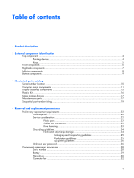
parts ...17 Sequential part number listing 19 4 Removal and replacement procedures Preliminary replacement requirements 22 Tools required ...22 Service considerations 22 Plastic parts 22 Cables and connectors 23 Drive replacement procedures 28 Serial number ...28 Battery ...29 Hard drive - HP G6000XX | Compaq Presario F500 and G6000 Notebook PC - Maintenance and Servic - Page 6
specifications 68 Hard drive specifications ...69 DVD±RW and CD-RW Super Multi Double-Layer Combo Drive and DVD-RW and CD-RW Combo Drive specifications ...70 System DMA specifications ...71 System interrupt specifications 72 System I/O address specifications 73 System memory map specifications - HP G6000XX | Compaq Presario F500 and G6000 Notebook PC - Maintenance and Servic - Page 7
partition on the hard drive 95 Updating reinstalled software 96 9 Connector pin assignments Audio-out (headphone) ...97 Audio-in (microphone) ...97 External monitor ...98 RJ-11 (modem) ...99 RJ-45 (network) ...99 S-Video-out ...100 Universal Serial Bus ...100 10 Power cord set requirements - HP G6000XX | Compaq Presario F500 and G6000 Notebook PC - Maintenance and Servic - Page 8
viii - HP G6000XX | Compaq Presario F500 and G6000 Notebook PC - Maintenance and Servic - Page 9
1 Product description Category Product Name Processors Chipset Graphics Panels Memory Description Compaq Presario F500 Notebook PC HP G6000 Notebook PC AMD Turion™ 64 Mobile Technology processors ● TL-58 (1.9-GHz, 1-GB L2 cache) ● TL-56 (1.8-GHz, 1-GB L2 cache) ● TL-52 (1.6-GHz, 1-MB - HP G6000XX | Compaq Presario F500 and G6000 Notebook PC - Maintenance and Servic - Page 10
Category Hard drives Optical drives Diskette drive Audio Modem Ethernet Wireless Ports Description ● 512-MB total system memory (512 MB × 1) ● 256-MB total system memory (256 MB x 1) ● Supports all 9.5-mm, SATA, 2.5-inch hard drives ● Parallel ATA ● 120-GB, 5400-rpm ● 100-GB, 5400-rpm ● 80-GB, 5400 - HP G6000XX | Compaq Presario F500 and G6000 Notebook PC - Maintenance and Servic - Page 11
plug with ground pin, supports 2-pin DC connector) Security Security cable slot Operating system Preinstalled: ● Windows Vista™ Premium ● Windows Vista Home Basic ● Free DOS Serviceability End-user replaceable parts: ● AC adapter ● Battery (system) ● Hard drive ● Memory module ● WLAN module - HP G6000XX | Compaq Presario F500 and G6000 Notebook PC - Maintenance and Servic - Page 12
TouchPad vertical scroll zone Function ● Blue: TouchPad is enabled. ● Amber: TouchPad is disabled. Moves the pointer and selects or activates items on the screen. Allows you to scroll left or right. Function like the left and right buttons on an external mouse. Enables/disables the TouchPad. Allows - HP G6000XX | Compaq Presario F500 and G6000 Notebook PC - Maintenance and Servic - Page 13
Power button Function Produce sound. Enables numeric lock, turns on the embedded numeric keypad, and turns on the num lock light. Can be used like the keys on an external numeric keypad. Move the cursor around the screen. Displays a shortcut menu for items beneath the pointer. Displays the Windows - HP G6000XX | Compaq Presario F500 and G6000 Notebook PC - Maintenance and Servic - Page 14
charged. If the computer is not plugged into an external power source, the light stays off until the battery reaches a low battery level. (3) Drive light Blinks when the hard drive or optical drive is being accessed. (4) Wireless switch Turns the wireless feature on or off, but does not create - HP G6000XX | Compaq Presario F500 and G6000 Notebook PC - Maintenance and Servic - Page 15
Right-side components Item Component (1) Optical drive (2) USB port (select models only) (3) Power connector (4) Security cable slot Function Reads an optical disc. Connects an optional USB device. Connects an AC adapter. Attaches an optional security cable to the - HP G6000XX | Compaq Presario F500 and G6000 Notebook PC - Maintenance and Servic - Page 16
(select models only) Function Connects an optional S-Video device, such as a television, VCR, camcorder, overhead projector, or video capture card. Connects an external VGA monitor or projector. Connects a network cable. Connects a modem cable. Connect optional USB devices. 8 Chapter 2 External - HP G6000XX | Compaq Presario F500 and G6000 Notebook PC - Maintenance and Servic - Page 17
compartment (5) Vents (5) (6) Hard drive bay Function Holds the battery. Releases the battery from the battery bay. Reads an optical disc. Contains the memory module slots, the WLAN module slot, and the RTC battery. NOTE: To prevent an unresponsive system, use only a wireless module authorized for - HP G6000XX | Compaq Presario F500 and G6000 Notebook PC - Maintenance and Servic - Page 18
3 Illustrated parts catalog Serial number location When ordering parts or requesting information, provide the computer serial number and model number located on the bottom of the computer. 10 Chapter 3 Illustrated parts catalog - HP G6000XX | Compaq Presario F500 and G6000 Notebook PC - Maintenance and Servic - Page 19
Computer major components Computer major components 11 - HP G6000XX | Compaq Presario F500 and G6000 Notebook PC - Maintenance and Servic - Page 20
Sempron 3400+ (1.8-GHz, 256-KB L2 cache) Plastics Kit (8a) Hard drive cover (includes one rubber foot and 2 captive screws, secured by C-clips) (8b) Memory module compartment cover (includes 3 captive screws, secured by C-clips) Spare part number 444896-002 442889-001 443153-001 442887-DH1 442887 - HP G6000XX | Compaq Presario F500 and G6000 Notebook PC - Maintenance and Servic - Page 21
USB/power connector board cable) 431445-001 (12) Base enclosure (include wireless switch and 4 rubber feet, not illustrated) 442890-001 Rubber Feet Kit (includes computer feet, not illustrated) 431431-001 (13) Hard drives (all 5400-rpm, include hard drive bracket and hard drive connector - HP G6000XX | Compaq Presario F500 and G6000 Notebook PC - Maintenance and Servic - Page 22
Ite Description m ** For use with F550-F579, G6000 models Spare part number 14 Chapter 3 Illustrated parts catalog - HP G6000XX | Compaq Presario F500 and G6000 Notebook PC - Maintenance and Servic - Page 23
-001 442877-001 431398-001 442878-001 Display enclosure (includes wireless antenna transceivers and cables), for defeatured models 442878-002 Display Cable Kit for Compaq models (not illustrated) 433287-001 Display Logo Kit, F500-F549 models (not illustrated) 442892-001* Display Logo Kit, F550 - HP G6000XX | Compaq Presario F500 and G6000 Notebook PC - Maintenance and Servic - Page 24
Plastics Kit Item Description Plastics Kit (1) Hard drive cover (includes 2 captive screws, secured by C-clips) (2) Memory module compartment cover (includes 2 captive screws, secured by C-clips) Spare part number 442891-001 16 Chapter 3 Illustrated parts catalog - HP G6000XX | Compaq Presario F500 and G6000 Notebook PC - Maintenance and Servic - Page 25
Mass storage devices Item Description (1) Hard drives (all 5400-rpm, include frame and hard drive connector) 120-GB 100-GB 80-GB (2) Optical drives (include bezel and bracket) DVD±RW and CD-RW Super Multi Double-Layer Combo Drive DVD-RW and CD-RW Combo Drive DVD±RW and CD-RW SuperMulti Double-Layer - HP G6000XX | Compaq Presario F500 and G6000 Notebook PC - Maintenance and Servic - Page 26
HP Remote Control HP Remote Control II Plus RF cable RF input adapter cable TV tuner remote control USB infrared emitter USB travel mouse Wired optical mouse Power cords screw ● Phillips PM2.0×4.0 screw ● Phillips PM2.0×3.0 screw Spare part number 371693-001 407313-001 435743-001 408485-001 407940- - HP G6000XX | Compaq Presario F500 and G6000 Notebook PC - Maintenance and Servic - Page 27
part number listing Spare part drive Wired headset with volume control Power cord for use in Canada, French Canada, Latin America, Thailand, and the United States Power cord for use in Australia Power cord , Qatar, South Korea, Uruguay, Venezuela HP Remote Control Composite S-Video and audio input - HP G6000XX | Compaq Presario F500 and G6000 Notebook PC - Maintenance and Servic - Page 28
cables) for models F500-F549 Display enclosure (includes wireless antenna transceivers and cables) for models F550-F579, G6000 512-GB memory module (PC2-5300, 667-GHz, 1 DIMM) 80-GB, 5400-rpm hard drive 120-GB, 5400-rpm hard drive DVD-RW and CD-RW Combo Drive 20 Chapter 3 Illustrated parts catalog - HP G6000XX | Compaq Presario F500 and G6000 Notebook PC - Maintenance and Servic - Page 29
Logo Kit for models F550-F570, G6000 Power button board (includes power button board cable) 1024-MB memory module (PC2-4200, 533-MHz, 1 DIMM) 100-GB, 5400-rpm hard drive 15.4-inch, WXGA, BrightView display assembly (includes display panel cable and wireless antenna transceivers and cables) 256-MB - HP G6000XX | Compaq Presario F500 and G6000 Notebook PC - Maintenance and Servic - Page 30
the work area to prevent damage. Plastic parts Using excessive force during disassembly and reassembly can damage plastic parts. Use care when handling the plastic parts. Apply pressure only at the points designated in the maintenance instructions. 22 Chapter 4 Removal and replacement procedures - HP G6000XX | Compaq Presario F500 and G6000 Notebook PC - Maintenance and Servic - Page 31
parts being removed or replaced. Handle flex cables with extreme care; these cables tear easily. Drive handling CAUTION: Drives are drives from any height onto any surface. After removing a hard drive, an optical drive, or a diskette drive, place it in a static-proof bag. Avoid exposing a hard drive - HP G6000XX | Compaq Presario F500 and G6000 Notebook PC - Maintenance and Servic - Page 32
but in many cases, ESD contains enough power to alter device parameters or melt silicon exposed to ESD may not be affected at all and can work perfectly throughout a normal cycle. Or the device may function normally V 2,000 V 3,500 V 7,000 V 5,000 V 24 Chapter 4 Removal and replacement procedures - HP G6000XX | Compaq Presario F500 and G6000 Notebook PC - Maintenance and Servic - Page 33
components, parts, and assemblies by the case or PCM laminate. Handle these items only at static-free workstations. ● Avoid contact with pins, leads, or circuitry. ● Turn off power and input signals before inserting or removing connectors or test equipment. Preliminary replacement requirements 25 - HP G6000XX | Compaq Presario F500 and G6000 Notebook PC - Maintenance and Servic - Page 34
resistance in the ground cords. To provide proper ground, boot straps) can be used at standing workstations and are compatible with most types of shoes or boots cords of one megohm resistance ● Static-dissipative tables or floor mats with hard ties to the ground ● Field service servicing has an - HP G6000XX | Compaq Presario F500 and G6000 Notebook PC - Maintenance and Servic - Page 35
the computer. 3. Disconnect the power cord. 4. Remove the battery (see Battery on page 29). 5. Remove the real-time clock (RTC) battery (see RTC battery on page 34). 6. Wait approximately 5 minutes. 7. Replace the RTC battery and reassemble the computer. 8. Connect AC power to the computer. Do not - HP G6000XX | Compaq Presario F500 and G6000 Notebook PC - Maintenance and Servic - Page 36
, that must be removed, replaced, or loosened when servicing the computer. Make special note of each screw and standoff size and location during removal and replacement. Serial number Report the computer serial number to HP when requesting information or ordering spare parts. The serial number is - HP G6000XX | Compaq Presario F500 and G6000 Notebook PC - Maintenance and Servic - Page 37
the power cord. Remove the battery: 1. Turn the computer upside down on a flat surface. 2. Slide the battery release latch (1) to release the battery. 3. Pivot the battery (2) upward and remove it from the computer. Reverse this procedure to install the battery. Component replacement procedures - HP G6000XX | Compaq Presario F500 and G6000 Notebook PC - Maintenance and Servic - Page 38
it down through the operating system. 2. Disconnect all external devices connected to the computer. 3. Disconnect the power cord. 4. Remove the battery (see Battery on page 29). Remove the hard drive: 1. Position the computer with the front toward you. 2. Loosen the two Phillips PM2.0×5.0 screws - HP G6000XX | Compaq Presario F500 and G6000 Notebook PC - Maintenance and Servic - Page 39
remove the hard drive bracket and connector, remove the six Phillips PM3.0×3.0 screws (1) that secure the bracket to the hard drive. 8. Lift the bracket (2) straight up to remove it from the hard drive. Reverse this procedure to reassemble and install the hard drive. Component replacement procedures - HP G6000XX | Compaq Presario F500 and G6000 Notebook PC - Maintenance and Servic - Page 40
the power cord. 4. Remove the battery (see Battery on page 29). Remove the memory module: 1. Position the computer with the front toward you. 2. Loosen the three Phillips PM2.0×5.0 screws (1) that secure the memory module compartment cover to the computer. 32 Chapter 4 Removal and replacement - HP G6000XX | Compaq Presario F500 and G6000 Notebook PC - Maintenance and Servic - Page 41
it to the right. 4. Remove the memory module compartment cover. NOTE: The memory module compartment cover is included in the Plastics Kit, spare part number 442891-001. 5. Spread the retaining tabs (1) on each side of the memory module socket to release the memory module. (The edge of the module - HP G6000XX | Compaq Presario F500 and G6000 Notebook PC - Maintenance and Servic - Page 42
external devices connected to the computer. 3. Disconnect the power cord. 4. Remove the battery (see Battery on page 29). 5. Remove the memory module compartment cover (see Memory module on page 32). Remove the RTC battery: 1. Disconnect the RTC battery cable (1) from the system board. 2. Remove the - HP G6000XX | Compaq Presario F500 and G6000 Notebook PC - Maintenance and Servic - Page 43
F500- power cord. 4. Remove the battery (see Battery on page 29). 5. Remove the memory module compartment cover (see Memory module on page 32). Remove the WLAN module: 1. Position the computer with the front toward you. 2. Disconnect the WLAN antenna cables (1) from the WLAN module. NOTE: The black - HP G6000XX | Compaq Presario F500 and G6000 Notebook PC - Maintenance and Servic - Page 44
drive NOTE: All optical drive spare part kits include an optical drive bezel. Description DVD±RW and CD-RW Super Multi Double-Layer Combo Drive DVD-RW and CD-RW Combo Drive . 3. Disconnect the power cord. 4. Remove the battery (see Battery on page 29). Remove the optical drive: 1. Position the - HP G6000XX | Compaq Presario F500 and G6000 Notebook PC - Maintenance and Servic - Page 45
4. Use the media tray frame to slide the optical drive (3) out of the computer. 5. Remove the optical drive. 6. If it is necessary to replace the optical drive bracket, position the optical drive with the bracket toward you. 7. Remove the two Phillips PM2.0×3.0 screws (1) that secure the bracket to - HP G6000XX | Compaq Presario F500 and G6000 Notebook PC - Maintenance and Servic - Page 46
includes display convertible hinge base cover) Spare part number 442889-001 Before removing the switch all external devices connected to the computer. 3. Disconnect the power cord. 4. Remove the battery (see Battery on page 29). Remove the switch cover: 1. Turn 4 Removal and replacement procedures - HP G6000XX | Compaq Presario F500 and G6000 Notebook PC - Maintenance and Servic - Page 47
(1) to which the LED board cable is attached and disconnect the cable (2). 7. Remove the switch cover. Reverse this procedure to install the switch cover. Component replacement procedures 39 - HP G6000XX | Compaq Presario F500 and G6000 Notebook PC - Maintenance and Servic - Page 48
Taiwan Thailand Turkey The United Kingdom The United States Spare part number 442887-171 442887-071 442887-AB1 442887-281 442887- devices connected to the computer. 3. Disconnect the power cord. 4. Remove the battery (see Battery on page 29). 5. Remove the switch cover and replacement procedures - HP G6000XX | Compaq Presario F500 and G6000 Notebook PC - Maintenance and Servic - Page 49
the keyboard cable is attached and disconnect the keyboard cable (2) from the system board. 9. Remove the keyboard. Reverse this procedure to install the keyboard. Component replacement procedures 41 - HP G6000XX | Compaq Presario F500 and G6000 Notebook PC - Maintenance and Servic - Page 50
board Description Power button board (includes power button board cable) Spare part number 443153-001 Before removing the power button board external devices connected to the computer. 3. Disconnect the power cord. 4. Remove the battery (see Battery on page 29). 5. Remove the following components: - HP G6000XX | Compaq Presario F500 and G6000 Notebook PC - Maintenance and Servic - Page 51
5. Remove the power button board (3). Reverse this procedure to install the power button board. Component replacement procedures 43 - HP G6000XX | Compaq Presario F500 and G6000 Notebook PC - Maintenance and Servic - Page 52
2. Disconnect all external devices connected to the computer. 3. Disconnect the power cord. 4. Remove the battery (see Battery on page 29). 5. Remove the memory module compartment cover (see Memory module on page 32). 6. Disconnect the wireless antenna cables from the WLAN module (see WLAN module on - HP G6000XX | Compaq Presario F500 and G6000 Notebook PC - Maintenance and Servic - Page 53
4. Remove the display assembly (2). 5. If it is necessary to replace any of the display assembly internal components, remove the eight rubber screw covers The display bezel rubber screw covers are included in the Display Screw Kit, spare part number 431400-001. Component replacement procedures 45 - HP G6000XX | Compaq Presario F500 and G6000 Notebook PC - Maintenance and Servic - Page 54
the bezel disengages from the display enclosure. 8. Remove the display bezel (3). NOTE: The display bezel is available using spare part number 453525-001. 9. If it is necessary to replace the display inverter, release the inverter (1) from the display enclosure as far as the display panel cable and - HP G6000XX | Compaq Presario F500 and G6000 Notebook PC - Maintenance and Servic - Page 55
(3) from the inverter. NOTE: The display inverter is available using spare part number 431391-001. 11. Remove the display inverter. 12. If it (2) from the display enclosure. NOTE: The display panel is available using spare part number 442877-002. 14. If it necessary to remove the display hinges, - HP G6000XX | Compaq Presario F500 and G6000 Notebook PC - Maintenance and Servic - Page 56
antenna cables (4) from the display enclosure. NOTE: The wireless antennae are included with the display enclosure and are also available using spare part number 431398-001. Reverse this procedure to reassemble and install the display assembly. 48 Chapter 4 Removal and replacement procedures - HP G6000XX | Compaq Presario F500 and G6000 Notebook PC - Maintenance and Servic - Page 57
cable) Spare part number 442888-001 power cord. 4. Remove the battery (see Battery on page 29). 5. Remove the following components: a. Hard drive (see Hard drive on page 30) b. Memory module compartment cover (see Memory module on page 32) c. Optical drive (see Optical drive replacement procedures 49 - HP G6000XX | Compaq Presario F500 and G6000 Notebook PC - Maintenance and Servic - Page 58
Hex HM5.0×7.0 standoffs 4. Turn the computer right-side up, with the front toward you. 5. Release and disconnect the following ZIF cables from the system board: (1) Power button board cable (2) TouchPad cable 50 Chapter 4 Removal and replacement procedures - HP G6000XX | Compaq Presario F500 and G6000 Notebook PC - Maintenance and Servic - Page 59
install the top cover. Audio board Description Audio board (includes audio board cable) Spare part number 431444-001 Before removing the audio board, follow these steps: 1. Shut down the external devices connected to the computer. 3. Disconnect the power cord. Component replacement procedures 51 - HP G6000XX | Compaq Presario F500 and G6000 Notebook PC - Maintenance and Servic - Page 60
battery (see Battery on page 29). 5. Remove the following components: a. Hard drive (see Hard drive on page 30) b. Memory module compartment cover (see Memory module on page 32) c. Optical drive (see Optical drive procedure to install the audio board. 52 Chapter 4 Removal and replacement procedures - HP G6000XX | Compaq Presario F500 and G6000 Notebook PC - Maintenance and Servic - Page 61
Disconnect all external devices connected to the computer. 3. Disconnect the power cord. 4. Remove the battery (see Battery on page 29). 5. Remove the following components: a. Hard drive (see Hard drive on page 30) b. Optical drive (see Optical drive on page 36) c. Keyboard (see Keyboard on page 40 - HP G6000XX | Compaq Presario F500 and G6000 Notebook PC - Maintenance and Servic - Page 62
3. Disconnect the USB board cable (3) and the power connector cable (4) from the USB/power connector board. Reverse this procedure to install the USB/power connector board. 54 Chapter 4 Removal and replacement procedures - HP G6000XX | Compaq Presario F500 and G6000 Notebook PC - Maintenance and Servic - Page 63
Disconnect all external devices connected to the computer. 3. Disconnect the power cord. 4. Remove the battery (see Battery on page 29). 5. Remove the following components: a. Hard drive (see Hard drive on page 30) b. Optical drive (see Optical drive on page 36) c. Switch cover (see Switch cover on - HP G6000XX | Compaq Presario F500 and G6000 Notebook PC - Maintenance and Servic - Page 64
the base enclosure. 3. Use the optical drive connector (1) to lift the right side of the system board (2) until it rests at an angle. 4. Remove the system board (3) by sliding it away from the top cover at an angle. 5. If it is necessary to replace the USB/power connector board cable or the audio - HP G6000XX | Compaq Presario F500 and G6000 Notebook PC - Maintenance and Servic - Page 65
6. Disconnect the USB/power connector board cable (1) and the audio board cable (2) from the system board. Reverse this procedure to install the system board. Component replacement procedures 57 - HP G6000XX | Compaq Presario F500 and G6000 Notebook PC - Maintenance and Servic - Page 66
pads) Spare part number 431450-001 power cord. 4. Remove the battery (see Battery on page 29). 5. Remove the following components: a. Hard drive (see Hard drive on page 30) b. Memory module compartment cover (see Memory module on page 32) c. Optical drive (see Optical drive replacement procedures - HP G6000XX | Compaq Presario F500 and G6000 Notebook PC - Maintenance and Servic - Page 67
the fan/heat sink assembly is reinstalled. Thermal pads and thermal paste are included with all fan/heat sink assembly, system board, and processor spare part kits. Reverse this procedure to install the fan/heat sink assembly. Component - HP G6000XX | Compaq Presario F500 and G6000 Notebook PC - Maintenance and Servic - Page 68
models Spare part number 448525-001 power cord. 4. Remove the battery (see Battery on page 29). 5. Remove the following components: a. Hard drive (see Hard drive on page 30) b. Memory module compartment cover (see Memory module on page 32) c. Optical drive (see Optical drive replacement procedures - HP G6000XX | Compaq Presario F500 and G6000 Notebook PC - Maintenance and Servic - Page 69
should be aligned with the triangle icon (4) embossed on the processor socket when you install the processor. Reverse this procedure to install the processor. Component replacement procedures 61 - HP G6000XX | Compaq Presario F500 and G6000 Notebook PC - Maintenance and Servic - Page 70
HP should repair this equipment. All troubleshooting replacement or Windows operating system is not working or will not load. NOTE: The fingerprint reader (select models only) does not work Windows opens and while "Press to enter setup" is displayed in the lower-left corner of the screen - HP G6000XX | Compaq Presario F500 and G6000 Notebook PC - Maintenance and Servic - Page 71
Utility, press f10 and then follow the instructions on the screen. Your preferences go into effect when the computer restarts in Windows. Navigating and selecting in the Setup Utility Because the Setup Utility is not Windows-based, it does not support the TouchPad. Navigation and selection are by - HP G6000XX | Compaq Presario F500 and G6000 Notebook PC - Maintenance and Servic - Page 72
Utility, press f10, and then follow the instructions on the screen. The Setup Utility default settings are set when hard drive self-test, a Network Service Boot, and settings for boot order preferences. The " to boot from LAN" message that is displayed in the lower-left corner of the screen - HP G6000XX | Compaq Presario F500 and G6000 Notebook PC - Maintenance and Servic - Page 73
f10, and then follow the instructions on the screen. - or - ◦ If the computer restarts in Windows. Setup Utility menus The specification information about the processor, memory size, system BIOS, and keyboard controller version (select models only). Security menu Select Administrator password Power - HP G6000XX | Compaq Presario F500 and G6000 Notebook PC - Maintenance and Servic - Page 74
Adapter boot―Enable/disable boot from Internal Network Adapter. ● Boot Order―Set the boot order for: ◦ USB Floppy ◦ ATAPI CD/DVD ROM Drive ◦ Hard drive ◦ USB Diskette on Key ◦ USB Hard drive ◦ Network adapter Enable/disable the Quick Launch Button tapping sound. Select the amount of video memory. To - HP G6000XX | Compaq Presario F500 and G6000 Notebook PC - Maintenance and Servic - Page 75
6 Specifications Computer specifications Dimensions Length Width Height (varies front to rear) Weight (with optical drive, hard drive, and battery) Input power Operating voltage Operating current Temperature Operating (not writing to optical disc) Operating (writing to optical disc) Nonoperating - HP G6000XX | Compaq Presario F500 and G6000 Notebook PC - Maintenance and Servic - Page 76
limits for plastic surfaces. The computer operates well within this range of temperatures. 15.4-inch, WXGA BrightView display specifications Dimensions Height Width Diagonal Number of colors Contrast ratio Brightness Pixel resolution Pitch Format Configuration Backlight Refresh rate Character - HP G6000XX | Compaq Presario F500 and G6000 Notebook PC - Maintenance and Servic - Page 77
5400 rpm 5400 rpm Operating temperature 5°C to 55°C (41°F to 131°F) *1 GB = 1 billion bytes when referring to hard drive storage capacity. Actual accessible capacity is less. NOTE: Certain restrictions and exclusions apply. Consult technical support for details. Hard drive specifications 69 - HP G6000XX | Compaq Presario F500 and G6000 Notebook PC - Maintenance and Servic - Page 78
CD-RW Super Multi Double-Layer Combo Drive and DVD-RW and CD-RW Combo Drive specifications Applicable disc Center hole diameter Disc diameter CD-RW 8X DVD+R 4X DVD+RW 8X DVD-R 4X DVD-RW 2.4X DVD+R(9) 5X DVD-RAM Transfer mode Startup time Stop time Read: Write: CD-DA, CD+(E)G, CD-MIDI, CD-TEXT, - HP G6000XX | Compaq Presario F500 and G6000 Notebook PC - Maintenance and Servic - Page 79
specifications Hardware DMA DMA0 DMA1* DMA2* DMA3 DMA4 DMA5* DMA6 DMA7 *PC Card controller can use DMA 1, 2, or 5. System function Not applicable Not applicable Not applicable Not applicable Direct memory access controller Available for PC Card Not assigned Not assigned System DMA specifications - HP G6000XX | Compaq Presario F500 and G6000 Notebook PC - Maintenance and Servic - Page 80
specifications Hardware IRQ System function IRQ0 IRQ1 System timer Standard 101-/102-Key or Microsoft® Natural Keyboard IRQ2 Cascaded IRQ4 COM1 IRQ6 Diskette drive configurations are IRQ5, IRQ7, IRQ9, IRQ10, or none. NOTE: PC Cards may assert IRQ3, IRQ4, IRQ5, IRQ7, IRQ9, IRQ10, IRQ11, or - HP G6000XX | Compaq Presario F500 and G6000 Notebook PC - Maintenance and Servic - Page 81
System I/O address specifications I/O address (hex) 000 - 00F 010 - 01F 020 - 021 022 - 024 025 - 03F 02E - 02F 040 - 05F 044 - 05F 060 Unused Secondary fixed disk controller Unused Primary fixed disk controller Unused JoyStick (decoded in ESS1688) Unused System I/O address specifications 73 - HP G6000XX | Compaq Presario F500 and G6000 Notebook PC - Maintenance and Servic - Page 82
Unused Reserved serial port Unused Infrared port Unused Unused Secondary diskette drive controller Parallel port (LPT1/default) Unused FM synthesizer-OPL3 Unused VGA Reserved (parallel port/no EPP support) VGA PC Card controller in CPU Unused Internal modem "A" diskette controller Serial port (COM1 - HP G6000XX | Compaq Presario F500 and G6000 Notebook PC - Maintenance and Servic - Page 83
00FFFFFF 04800000-07FFFFFF 04800000-07FFFFFF 08000000-080FFFFF 08200000-FFFEFFFF FFFF0000-FFFFFFFF System function Base memory Video memory Video BIOS Unused System BIOS Extended memory Super extended memory Unused Video memory (direct access) Unused System BIOS System memory map specifications 75 - HP G6000XX | Compaq Presario F500 and G6000 Notebook PC - Maintenance and Servic - Page 84
Screw listing This section provides specification and reference information for the screws and screw locks used in the computer. All screws and screw locks listed in this section are available in the Screw Kit, spare part number 431433-001, and the Display Screw Kit, spare part number 431400-001. 76 - HP G6000XX | Compaq Presario F500 and G6000 Notebook PC - Maintenance and Servic - Page 85
Phillips PM2.0×5.0 captive screw Color Black Quantity 5 Length 5.0 mm Thread 2.0 mm Head width 5.0 mm Where used: (1) Two screws (secured by C-clips) that secure the hard drive cover to the computer (2) Three screws (secured by C-clips) that secure the memory module compartment cover to the - HP G6000XX | Compaq Presario F500 and G6000 Notebook PC - Maintenance and Servic - Page 86
Phillips PM3.0×3.0 screw Color Silver Quantity 6 Length 3.0 mm Thread 3.0 mm Head width 5.0 mm Where used: 6 screws that secure the hard drive bracket to the hard drive 78 Chapter 7 Screw listing - HP G6000XX | Compaq Presario F500 and G6000 Notebook PC - Maintenance and Servic - Page 87
Phillips PM2.0×3.0 screw Color Black Quantity 9 Length 3.0 mm Thread 2.0 mm Where used: 2 screws that secure the WLAN module to the computer Head width 4.5 mm Where used: 2 screws that secure the optical drive bracket to the optical drive Phillips PM2.0×3.0 screw 79 - HP G6000XX | Compaq Presario F500 and G6000 Notebook PC - Maintenance and Servic - Page 88
Where used: One screw that secures the power button board to the computer Where used: 4 screws that secure the display hinges to the display panel 80 Chapter 7 Screw listing - HP G6000XX | Compaq Presario F500 and G6000 Notebook PC - Maintenance and Servic - Page 89
Phillips PM2.5×7.0 screw Color Black Quantity 25 Length 7.0 mm Thread 2.5 mm Where used: (1) One screw that secures the optical drive to the computer (2) Three screws that secure the keyboard to the computer Head width 5.0 mm Where used: 4 screws that secure the display assembly to the - HP G6000XX | Compaq Presario F500 and G6000 Notebook PC - Maintenance and Servic - Page 90
Where used: 8 screws that secure the display bezel to the display assembly Where used: 9 screws that secure the top cover to the computer 82 Chapter 7 Screw listing - HP G6000XX | Compaq Presario F500 and G6000 Notebook PC - Maintenance and Servic - Page 91
Phillips PM2.5×10.0 screw Color Black Quantity 2 Length 10.0 mm Thread 2.5 mm Where used: 2 screws that secure the switch cover to the computer Head width 5.0 mm Phillips PM2.5×10.0 screw 83 - HP G6000XX | Compaq Presario F500 and G6000 Notebook PC - Maintenance and Servic - Page 92
Phillips PM2.5×5.0 Screw Color Silver Quantity 19 Length 5.0 mm Thread 2.5 mm Where used: (1) One screw that secures the switch cover to the computer (2) Six screws that secure the top cover to the base enclosure Head Width 5.0 mm Where used: 6 screws that secure the display panel to the - HP G6000XX | Compaq Presario F500 and G6000 Notebook PC - Maintenance and Servic - Page 93
Where used: 2 screws that secure the top cover to the base enclosure Where used: (1) Two screws that secure the audio board to the base enclosure (2) Two screws that secure the USB/power connector board to the base enclosure Phillips PM2.5×5.0 Screw 85 - HP G6000XX | Compaq Presario F500 and G6000 Notebook PC - Maintenance and Servic - Page 94
Phillips PM2.0×4.0 Screw Color Silver Quantity 2 Length 4.0 mm Thread 2.0 mm Head width 5.0 mm Where used: 2 screws that secure the wireless antenna transceivers to the display enclosure 86 Chapter 7 Screw listing - HP G6000XX | Compaq Presario F500 and G6000 Notebook PC - Maintenance and Servic - Page 95
Phillips PM2.5×4.0 screw Color Silver Quantity 5 Length 4.0 mm Thread 2.5 mm Where used: 3 screws that secure the top cover to the base enclosure Head width 5.0 mm Where used: 2 screws that secure the system board to the base enclosure Phillips PM2.5×4.0 screw 87 - HP G6000XX | Compaq Presario F500 and G6000 Notebook PC - Maintenance and Servic - Page 96
Hex HM5.0×7.0 Standoff Color Silver Quantity 2 Length 7.0 mm Thread 2.5 mm Head width 5.0 mm 88 Chapter 7 Screw listing - HP G6000XX | Compaq Presario F500 and G6000 Notebook PC - Maintenance and Servic - Page 97
Phillips PM2.0×6.0 screw Color Black Quantity 2 Length 6.0 mm Thread 2.0 mm Where used: 2 screws that secure the top cover to the base enclosure Head width 5.0 mm Phillips PM2.0×6.0 screw 89 - HP G6000XX | Compaq Presario F500 and G6000 Notebook PC - Maintenance and Servic - Page 98
Phillips PM2.5×5.0 captive screw Color Silver Quantity 5 Length 5.0 mm Thread 2.5 mm Head width 5.0 mm Where used: 5 screws that secure the fan/heat sink assembly to the system board 90 Chapter 7 Screw listing - HP G6000XX | Compaq Presario F500 and G6000 Notebook PC - Maintenance and Servic - Page 99
). Recovery discs are used to start up (boot) your computer and restore the operating system and instability. Recovery Manager works from a dedicated recovery partition on the hard drive or from recovery in a window, toolbar, or menu bar by taking a screen shot of your settings. The screen shot can - HP G6000XX | Compaq Presario F500 and G6000 Notebook PC - Maintenance and Servic - Page 100
the entire screen, press fn+prt sc. c. Open a word-processing document, and then select Edit> Paste. Using system restore points When you back up your system, you are creating a system restore point. A system restore point allows you to save and name a snapshot of your hard drive at a specific point - HP G6000XX | Compaq Presario F500 and G6000 Notebook PC - Maintenance and Servic - Page 101
into the computer optical drive. ● If necessary, battery power, you will be prompted to connect to AC power before you can go to the next step. 3. Click Recovery disc creation, and then click Next. 4. Follow the on-screen instructions. Reinstalling software programs and drivers If a program or driver - HP G6000XX | Compaq Presario F500 and G6000 Notebook PC - Maintenance and Servic - Page 102
experience system failure or instability. Recovery Manager works from recovery discs that you create or from a dedicated recovery partition on the hard drive. NOTE: Windows has its own built-in repair features, such as System Restore and driver rollback capabilities. If you have not already tried - HP G6000XX | Compaq Presario F500 and G6000 Notebook PC - Maintenance and Servic - Page 103
personal files. 2. Insert the first recovery disc into the optical drive and restart the computer. 3. Follow the on-screen instructions. Recovering from the partition on the hard drive You can perform a recovery from the partition on the hard drive from either the Start button or f11. To restore the - HP G6000XX | Compaq Presario F500 and G6000 Notebook PC - Maintenance and Servic - Page 104
the operating system and other software provided on your computer: ▲ Select Start > Help and Support. To update optional software, follow the instructions provided by the software manufacturer. Some programs include an update feature you can access from a Help button or menu within the program. 96 - HP G6000XX | Compaq Presario F500 and G6000 Notebook PC - Maintenance and Servic - Page 105
9 Connector pin assignments Audio-out (headphone) Pin Signal 1 Audio out, left channel 2 Audio out, right channel 3 Ground Audio-in (microphone) Pin Signal 1 Audio signal in 2 Audio signal in 3 Ground Audio-out (headphone) 97 - HP G6000XX | Compaq Presario F500 and G6000 Notebook PC - Maintenance and Servic - Page 106
External monitor Pin Signal 1 Red analog 2 Green analog 3 Blue analog 4 Not connected 5 Ground 6 Ground analog 7 Ground analog 8 Ground analog 9 +5 VDC 10 Ground 11 Monitor detect 12 DDC 2B data 13 Horizontal sync 14 Vertical sync 15 DDC 2B clock 98 Chapter 9 - HP G6000XX | Compaq Presario F500 and G6000 Notebook PC - Maintenance and Servic - Page 107
RJ-11 (modem) Pin 1 2 3 4 5 6 RJ-45 (network) Signal Unused Tip Ring Unused Unused Unused Pin Signal 1 Transmit + 2 Transmit - 3 Receive + 4 Unused 5 Unused 6 Receive - 7 Unused 8 Unused RJ-11 (modem) 99 - HP G6000XX | Compaq Presario F500 and G6000 Notebook PC - Maintenance and Servic - Page 108
S-Video-out Pin Signal 1 S-VHS color (C) signal 2 Composite video signal 3 S-VHS intensity (Y) signal 4 S-VHS color ground 5 TV-CD 6 S-VHS intensity ground 7 Composite video ground Universal Serial Bus Pin Signal 1 +5 VDC 2 Data - 3 Data + 4 Ground 100 Chapter 9 Connector - HP G6000XX | Compaq Presario F500 and G6000 Notebook PC - Maintenance and Servic - Page 109
sets must be approved by an acceptable accredited agency responsible for evaluation in the country or region where the power cord set will be used. ● The power cord sets must have a minimum current capacity of 10 amps and a nominal voltage rating of 125 or 250 V AC, as required by each country or - HP G6000XX | Compaq Presario F500 and G6000 Notebook PC - Maintenance and Servic - Page 110
Requirements for specific countries or regions Country/region Accredited agency Applicable note number Australia EANSW region where it will be used. 5. The flexible cord must be Type VCTF, 3-conductor, 0.75 mm² conductor size. Power cord set fittings (appliance coupler and wall plug) must - HP G6000XX | Compaq Presario F500 and G6000 Notebook PC - Maintenance and Servic - Page 111
11 Recycling Battery When a battery has reached the end of its useful life, do not dispose of the battery in general household waste. Follow the local laws and regulations in your area for computer battery disposal. Battery 103 - HP G6000XX | Compaq Presario F500 and G6000 Notebook PC - Maintenance and Servic - Page 112
be exercised when removing these components. NOTE: Materials Disposal. This HP product contains mercury in the backlight in the display assembly that might . The procedures provided in this appendix are general disassembly instructions. Specific details, such as screw sizes, quantities, and locations - HP G6000XX | Compaq Presario F500 and G6000 Notebook PC - Maintenance and Servic - Page 113
Perform the following steps to disassemble the display assembly: 1. Remove all screw covers (1) and screws (2) that secure the display bezel to the display assembly. 2. Lift up and out on the left - HP G6000XX | Compaq Presario F500 and G6000 Notebook PC - Maintenance and Servic - Page 114
4. Disconnect all display panel cables (1) from the display inverter and remove the inverter (2). 5. Remove all screws (1) that secure the display panel assembly to the display enclosure. 6. Remove the display panel assembly (2) from the display enclosure. 7. Turn the display panel assembly upside - HP G6000XX | Compaq Presario F500 and G6000 Notebook PC - Maintenance and Servic - Page 115
10. Remove the display panel frame (2) from the display panel. 11. Remove the screws (1) that secure the backlight cover to the display panel. 12. Lift the top edge of the backlight cover (2) and swing it forward. 13. Remove the backlight cover. 14. Turn the display panel right-side up. Display 107 - HP G6000XX | Compaq Presario F500 and G6000 Notebook PC - Maintenance and Servic - Page 116
15. Remove the backlight cables (1) from the clip (2) in the display panel. 16. Turn the display panel upside down. 17. Remove the backlight frame from the display panel. WARNING! The backlight contains mercury. Caution should be exercised when removing and handling the backlight to avoid damaging - HP G6000XX | Compaq Presario F500 and G6000 Notebook PC - Maintenance and Servic - Page 117
18. Slide the backlight out of the backlight frame. 19. Disconnect the display cable (1) from the LCD panel. 20. Remove the screws (2) that secure the LCD panel to the display rear panel. 21. Release the LCD panel (3) from the display rear panel. 22. Release the tape (4) that secures the LCD panel - HP G6000XX | Compaq Presario F500 and G6000 Notebook PC - Maintenance and Servic - Page 118
number 13, 21 battery location 9 removal 29 spare part number 13, 20, 29 battery light 6 battery release latch 9 bezel illustrated 15 spare part number 15 boot options 66 boot order 66 bottom components 9 button sound 66 C Cable Kit, spare part number 13 cables, service considerations 23 caps lock - HP G6000XX | Compaq Presario F500 and G6000 Notebook PC - Maintenance and Servic - Page 119
5 num lock 5 Windows applications 5 Windows logo 5 L language support 63, 66 left-side components 8 lights battery 6 drive 6 power 6 wireless 6 Logo Kit, spare part number 21 M Main menu 65 mass storage devices, spare part numbers 17 memory map specifications 75 memory module product description - HP G6000XX | Compaq Presario F500 and G6000 Notebook PC - Maintenance and Servic - Page 120
2 display panel 1 Ethernet 2 graphics 1 hard drives 2 keyboard 3 memory module 1 modem module 2 operating system 3 optical drives 2 pointing devices 3 ports 2 power requirements 3 processors 1 product name 1 security 3 serviceability 3 wireless 2 product name 1 R recovery discs 93 recovery partition - HP G6000XX | Compaq Presario F500 and G6000 Notebook PC - Maintenance and Servic - Page 121
digital drive, spare part number 19 USB infrared emitter, spare part number 19 USB/power connector board removal 53 spare part number 13, 20, 53 V vents 9 video memory 66 W Windows applications key 5 Windows logo key 5 wireless antenna removal 48 spare part number 20, 48 wireless light 6 wireless - HP G6000XX | Compaq Presario F500 and G6000 Notebook PC - Maintenance and Servic - Page 122
-
 1
1 -
 2
2 -
 3
3 -
 4
4 -
 5
5 -
 6
6 -
 7
7 -
8
-
9
-
10
-
11
-
12
-
13
-
14
-
15
-
16
-
17
-
18
-
19
-
20
-
21
-
22
-
23
-
24
-
25
-
26
-
27
-
28
-
29
-
30
-
31
-
32
-
33
-
34
-
35
-
36
-
37
-
38
-
39
-
40
-
41
-
42
-
43
-
44
-
45
-
46
-
47
-
48
-
49
-
50
-
51
-
52
-
53
-
54
-
55
-
56
-
57
-
58
-
59
-
60
-
61
-
62
-
63
-
64
-
65
-
66
-
67
-
68
-
69
-
70
-
71
-
72
-
73
-
74
-
75
-
76
-
77
-
78
-
79
-
80
-
81
-
82
-
83
-
84
-
85
-
86
-
87
-
88
-
89
-
90
-
91
-
92
-
93
-
94
-
95
-
96
-
97
-
98
-
99
-
100
-
101
-
102
-
103
-
104
-
105
-
106
-
107
-
108
-
109
-
110
-
111
-
112
-
113
-
114
-
115
-
116
-
117
-
118
-
119
-
120
-
121
-
122
 |
 |

Compaq Presario F500 Notebook PC and HP
G6000 Notebook PC
Maintenance and Service Guide