HP G6000XX Compaq Presario F500 and G6000 Notebook PC - Maintenance and Servic - Page 58
Two Hex HM5.0×7.0 standoffs, Six Phillips PM2.5×5.0 screws
 |
View all HP G6000XX manuals
Add to My Manuals
Save this manual to your list of manuals |
Page 58 highlights
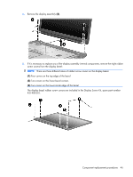
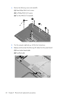
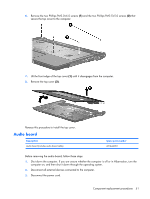
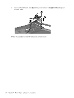
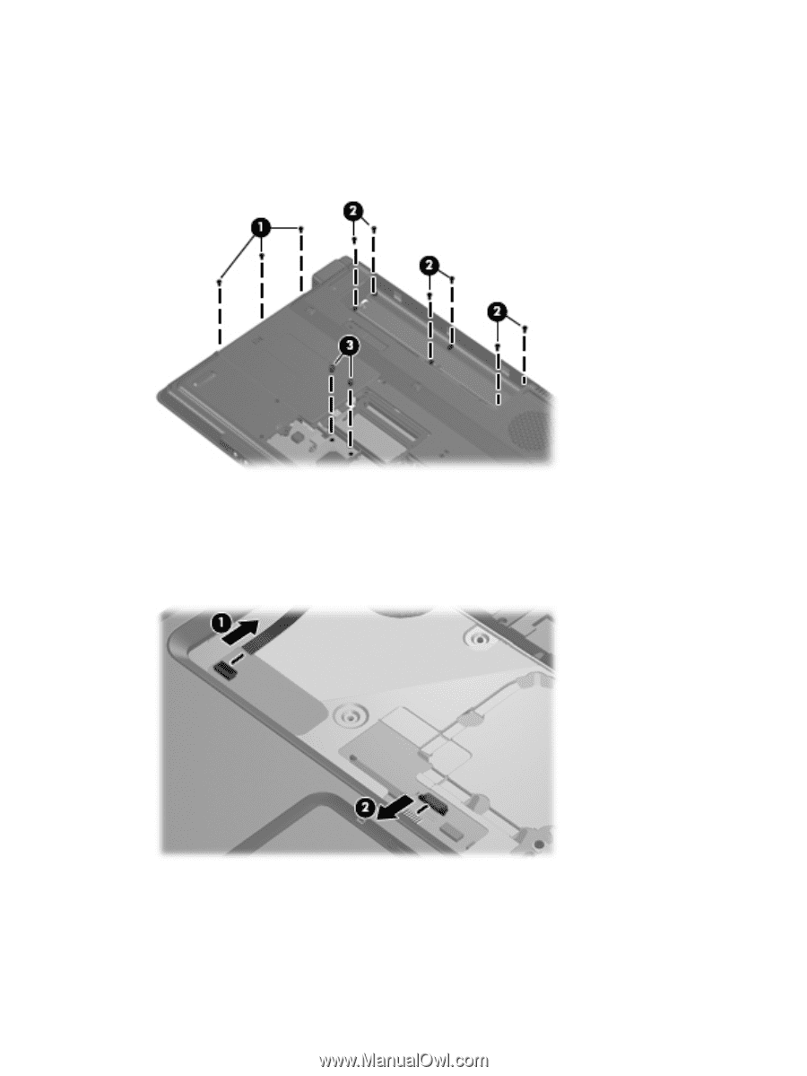
3. Remove the following screws and standoffs: (1) Three Phillips PM2.5×4.0 screws (2) Six Phillips PM2.5×5.0 screws (3) Two Hex HM5.0×7.0 standoffs 4. Turn the computer right-side up, with the front toward you. 5. Release and disconnect the following ZIF cables from the system board: (1) Power button board cable (2) TouchPad cable 50 Chapter 4 Removal and replacement procedures
-
 1
1 -
2
-
3
-
4
-
5
-
6
-
7
-
8
-
9
-
10
-
11
-
12
-
13
-
14
-
15
-
16
-
17
-
18
-
19
-
20
-
21
-
22
-
23
-
24
-
25
-
26
-
27
-
28
-
29
-
30
-
31
-
32
-
33
-
34
-
35
-
36
-
37
-
38
-
39
-
40
-
41
-
42
-
43
-
44
-
45
-
46
-
47
-
48
-
49
-
50
-
51
-
52
-
 53
53 -
 54
54 -
 55
55 -
 56
56 -
 57
57 -
 58
58 -
 59
59 -
 60
60 -
 61
61 -
 62
62 -
 63
63 -
64
-
65
-
66
-
67
-
68
-
69
-
70
-
71
-
72
-
73
-
74
-
75
-
76
-
77
-
78
-
79
-
80
-
81
-
82
-
83
-
84
-
85
-
86
-
87
-
88
-
89
-
90
-
91
-
92
-
93
-
94
-
95
-
96
-
97
-
98
-
99
-
100
-
101
-
102
-
103
-
104
-
105
-
106
-
107
-
108
-
109
-
110
-
111
-
112
-
113
-
114
-
115
-
116
-
117
-
118
-
119
-
120
-
121
-
122
 |
 |
3
.
Remove the following screws and standoffs:
(1)
Three Phillips PM2.5×4.0 screws
(2)
Six Phillips PM2.5×5.0 screws
(3)
Two Hex HM5.0×7.0 standoffs
4
.
Turn the computer right-side up, with the front toward you.
5
.
Release and disconnect the following ZIF cables from the system board:
(1)
Power button board cable
(2)
TouchPad cable
50
Chapter
4
Removal and replacement procedures